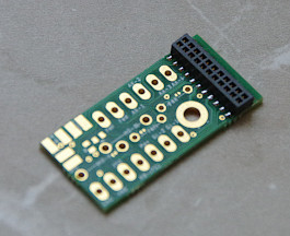
For installation in locomotives that do not already have a suitable plug or socket, we have created an adapter with a PluX22 interface.
| Property | Description |
|---|---|
| Optimized for | Locomotives without a digital interface |
| Dimensions | 30 x 14.5 mm |
| Interfaces | PluX22 socket, optional SUSI3-Classic socket |
We offer the adapter in three variants:
| With PluX22 socket only | With PluX22 socket and SUSI3-Classic | With PluX22 socket, SUSI3-Classic, and screw terminals |
|---|---|---|
 |
 |
 |
| Buy now | Buy now | Buy now |
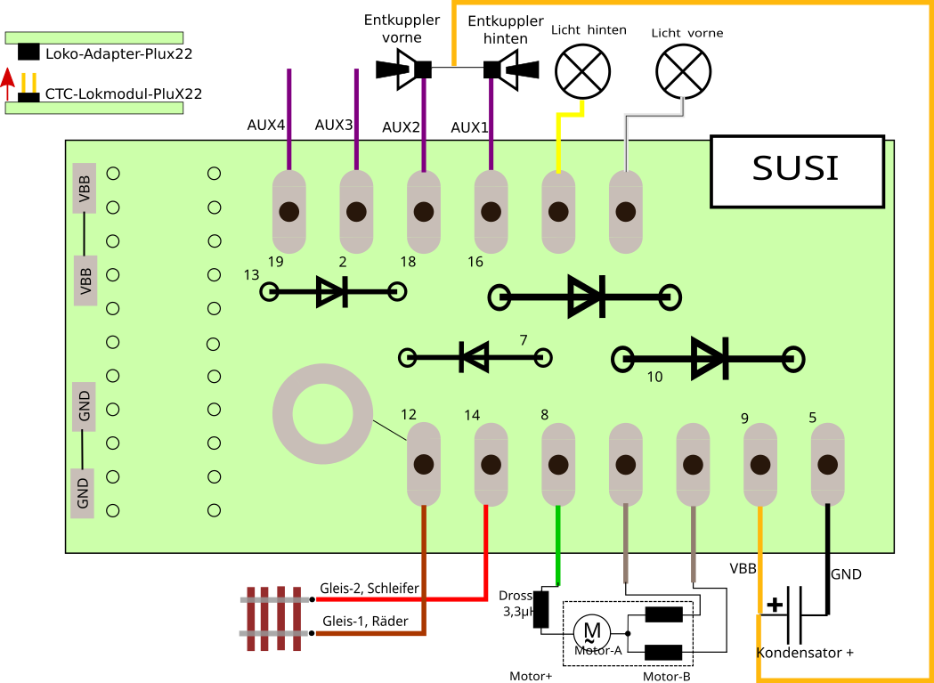
The circuit board also provides space for:
- 2 diodes for connecting motors with field coils (e.g., older Märklin locomotives).
- One diode each for front and rear lights for connecting lighting with only one wire (second pole on the housing).
Notes:
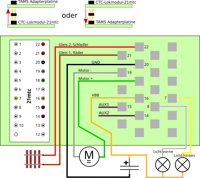
- The standard PluX22 does not have suitable connections for IR receivers and NFC readers. Therefore, these are connected via the separate socket on the CTC locomotive module.
- In the locomotive module-PluX22, the headlight is configured as a switch against ground (low-side). If it needs to switch against the positive pole (high-side), the light must be removed in the configuration dialog and replaced with a high-side version. See the conversion of the Märklin BR53 (Borsig I).
- The diodes (Analog locomotive conversion kit) must be ordered separately and soldered in manually. The PluX22 socket is always pre-soldered.
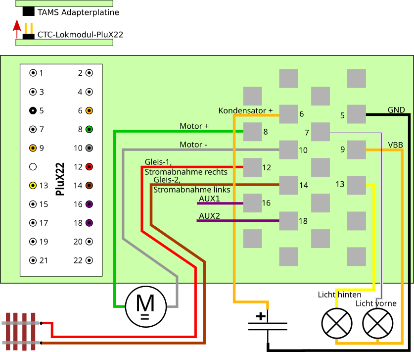
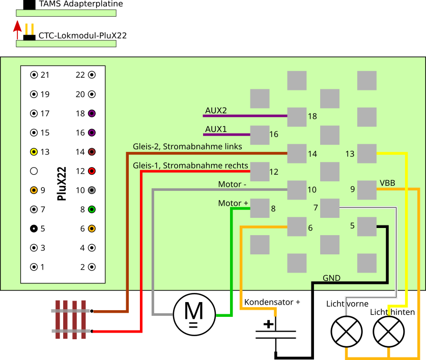
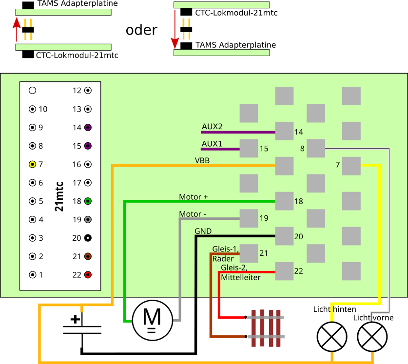
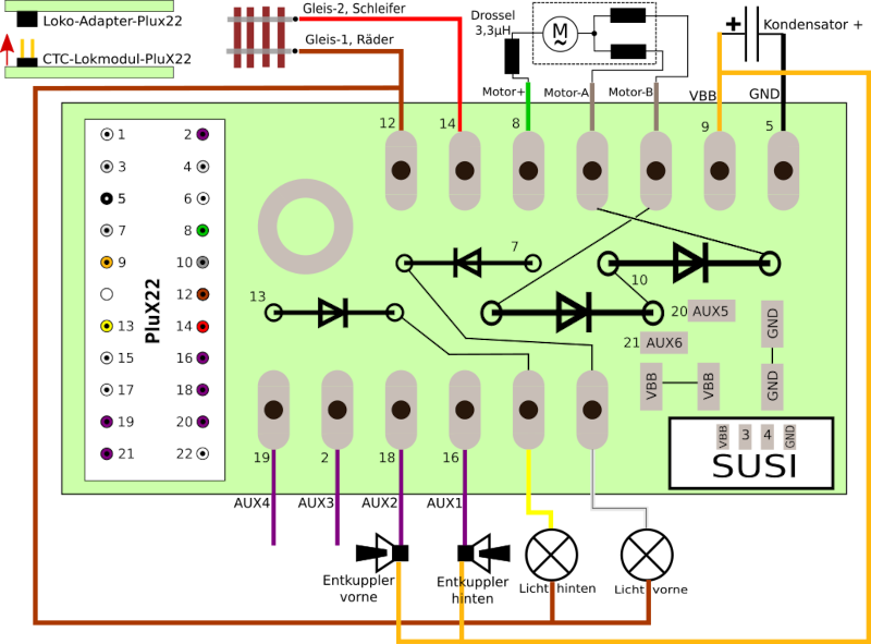
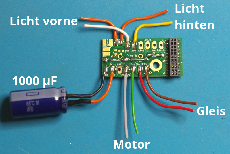
Wiring
The example shows the wiring of an old analog locomotive with a field coil and electrical uncouplers at the front and rear:
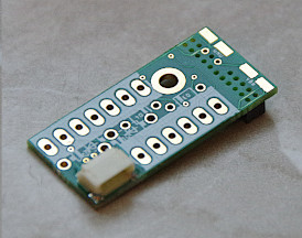
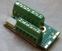
Here is the rear view, as it would appear, for example, in the screw terminal variant:
The hole in the circuit board is electrically connected to track 1, so this connection can alternatively be made by screwing it to the housing. For old Märklin locomotives, the board can be screwed in where the switch was previously mounted. A cable to the wheels/housing is then unnecessary.
The following image shows the adapter with all diodes soldered in place:
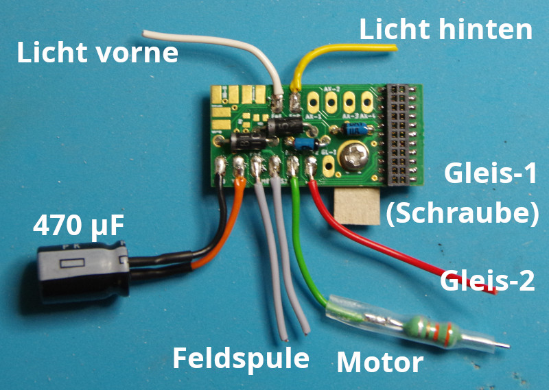
Note: When screwing in, ensure that—especially at the rear—no short circuit to the locomotive housing occurs. In the image, this was resolved by placing a piece of cardboard behind the adapter.
If the locomotive has a permanent magnet, the two right diodes are omitted, and the upper one is replaced with a wire bridge. The motor is then connected to Motor+ and Motor-A. Motor-B remains unconnected.
If the front and rear lights have two wires (i.e., no connection to the locomotive housing), the small blue diodes can be replaced with wire bridges.
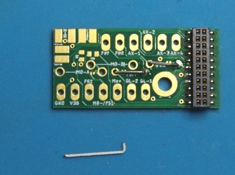
In the following image, all bridges are soldered in place:
Tip for soldering bridges: Bend one end of the wire pieces at a right angle using pliers. Then insert the bent side into the circuit board and solder it. Only then trim the wire to the correct length and finally solder the other end: