The BR 53 is our first conversion of an analog M�rklin locomotive using our own adapter for PluX22.
Note: This conversion is based on corrected IO configuration and product catalog included in the CTC-App from version 4.30 onwards.
The locomotive housing is opened by pulling off the cover directly in front of the cab.
Below it is the first of three screws.
The other two are located under the leading axle.
Once all three screws are removed, the boiler and cab can be taken off.
In the tender are the switch and tail light.
To open the tender, we remove the screw located underneath between the tender’s bogies.
Then the top part of the tender can be lifted upwards.

For this conversion, we need all the diodes included in the “Conversion Kit-Analog”.
They are placed on the “Adapter Board PluX22” and then soldered.
It is essential to pay attention to the position of the marking ring (see picture).
On the side of the motor that is not connected to the field coil, we attach the choke.
The third hand holds the adapter board for us while we solder the wires from the track and to the motor.
In our instance, the original wires were in very poor condition, so we replaced them with new wires:
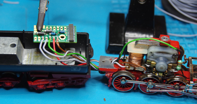
The wires are:
- Center conductor red
- Housing/wheels brown
- Field coil left/right gray
- Choke on motor green
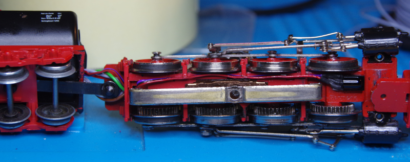
We place the IR receiver in front of the slider.
This way, we can run the wire from the electronics in the tender through the existing hole at the end of the locomotive chassis:
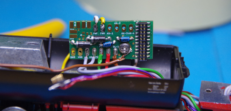
Then we solder the wires from the two lights (front white, rear yellow) to the adapter board:
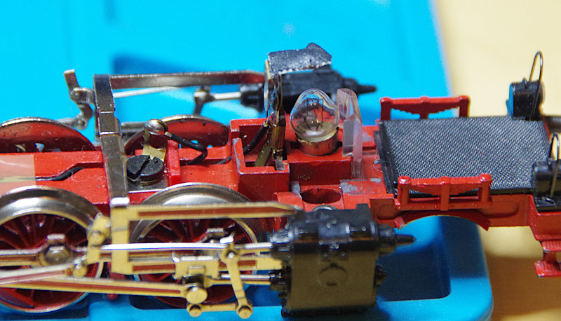
Unfortunately, the front light and the smoke generator share the same wire and metal contact.
Therefore, we forgo the smoke function and cover the contact with insulating tape:
Alternatively, we could consider how to separate the lamp and smoke generator connection and then connect the smoke generator to AUX1 with a newly laid wire and diode.
Finally, the buffer capacitor is soldered on (plus orange, minus black):
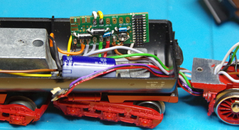
Now the CTC locomotive module PluX22 can be plugged into the adapter and then the IR receiver onto the locomotive module:
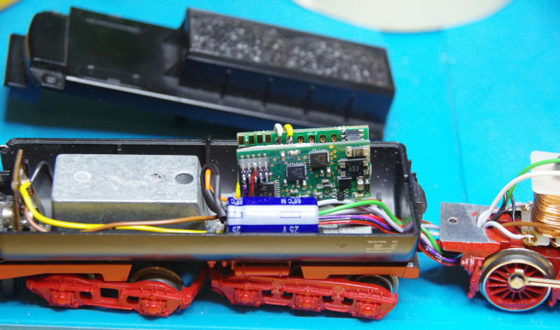
Before we reassemble the locomotive, we place it on a roller test stand.
There we configure the locomotive module and test if everything works.
Replace IO-Config
If you have a CTC locomotive module PluX22 that was delivered before June 27, 2025, you need to replace the IO-Config of the locomotive module for this conversion. You can also do this if the locomotive module is already installed.
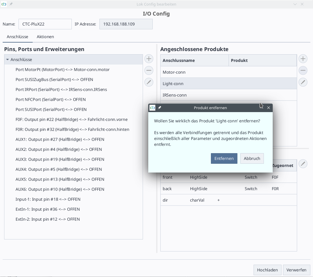
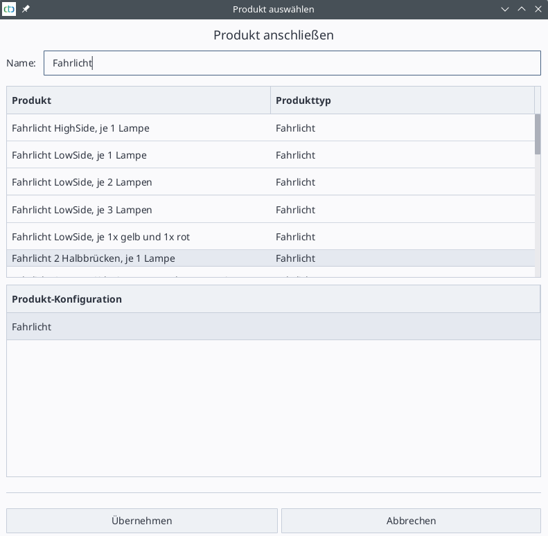
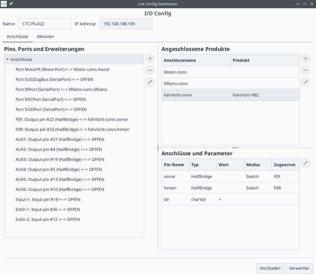
The reason for this is that, until now, we have set the switching outputs as LowSide (and only used them that way). For the conversion of the analog locomotive, we now need the property of the half-bridge to switch against plus (HighSide).
You can recognize the old IO-Config by the fact that in the dialog “Change Config” behind the switching outputs (e.g., F0F and FoR) in parentheses “LowSide” is indicated instead of “HalfBridge.”
To replace the IO-Config, open the Config dialog of the locomotive and click on the button “Replace IO-Config.” The following dialog opens:
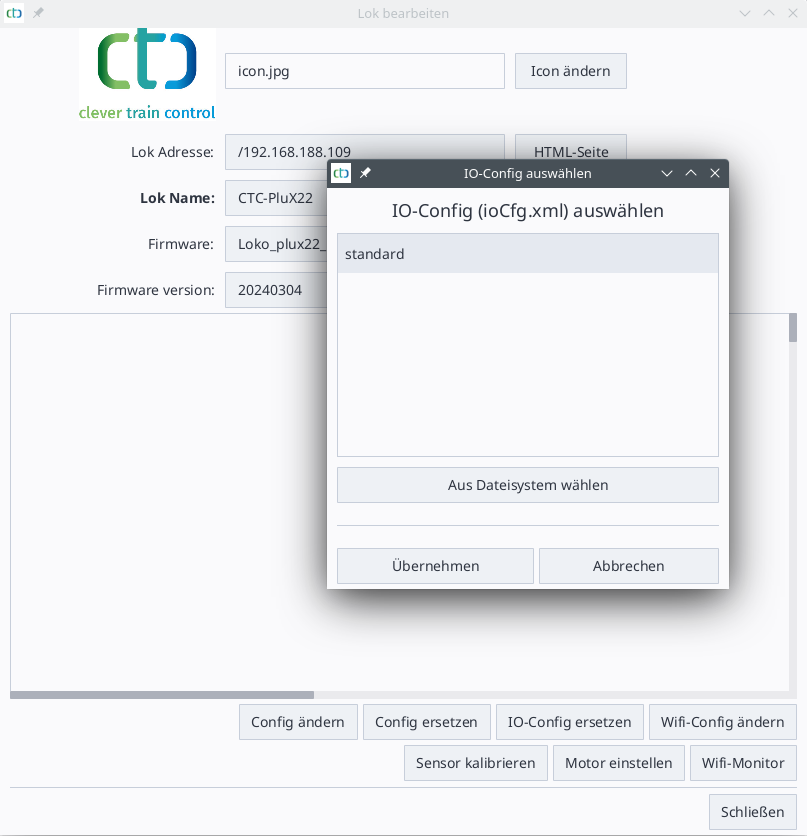
There, we select the configuration “standard” and click on “Apply.”null## Light Configuration
