


Common Features of All CTC Switching Modules
| Feature | Description |
|---|---|
| Input Voltage | approx. 9 V to 24 V DC, digital current – (AC only with smoothing capacitor) |
| Interfaces | CTC-IR-balise |
From February 2025, we will include a TVS diode with all CTC switching modules. For more details, see the section “Overvoltage Protection” on the page “Power Supply and Router”.
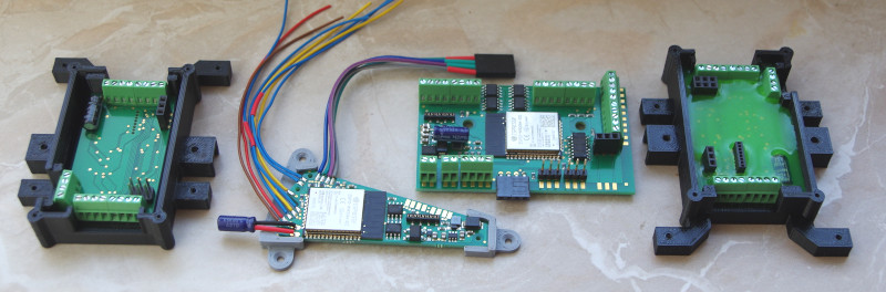
Overview of CTC Switching Modules (from €40)
For switching turnouts, signals, lights, etc., the following CTC modules are available:
| CTC Turnout Module | Optimized for | Dimensions | Switching Outputs | Servos | Sensor Inputs | IR Balises | Max. Total Current |
|---|---|---|---|---|---|---|---|
| CTC-Weichenmodul | Solenoid actuators, Märklin C-track | 68 x 26 mm | 4x 0.5 A Lowside | - | - | 2 | 2 A |
| CTC-Weichenmodul-G | Garden railway, motor drives | 53 x 31 mm | 4x 2 A Half-bridge | 2 | 4 | 2 | 3 A |
| CTC-Multi-I/O-Board | Solenoid actuators, servos | 74 x 46 mm | 8x 0.5 A Lowside | 2 | 4 | 2 | 2 A |
Notes:
- Operating CTC modules on alternating current (AC) or unfiltered direct current without an additional capacitor will cause irreversible damage to the CTC module.
- Switching outputs are differentiated by whether they switch ground/negative (LowSide) or the positive pole (HighSide). Especially with LED boards, one pole often has a common line. In such cases, it is crucial whether the module’s switching outputs are designed as HighSide or LowSide.
- A half-bridge can switch between the positive and negative poles but is never fully off. Particularly so-called solenoid actuators (e.g., classic turnout drives) can suffer permanent damage if incorrectly configured on a half-bridge and should therefore not be connected to one.
- Servos require an additional power supply module.
Installation Guides
Turnouts
The following installation guides are available for the CTC turnout module:
Guides for the CTC turnout module-G:
Servos
- Overview of operating servos with CTC
Turntable
A turntable can also be connected to the CTC turnout module G. For details, see Anschluss Fleischmann-Drehscheibe