| Feature | Description |
|---|---|
| Processor | Espressif ESP-32 |
| Dimensions | 68 x 26 mm - same shape as Märklin C-Track Decoder |
| Input Voltage | approx. 9V to 24V DC (smoothed DC), digital power, AC with buffer capacitor |
| Power Outputs | 4 |
| Max. Total Current | 2 A |
| Interfaces | 2 CTC IR balises (each max. 12mA), I2C bus |
| Current online passive | approx. 20mA at 16V |
| Current booting | approx. 50mA at 16V plus switching current for initializing the outputs |
You can get the CTC turnout module in three versions:
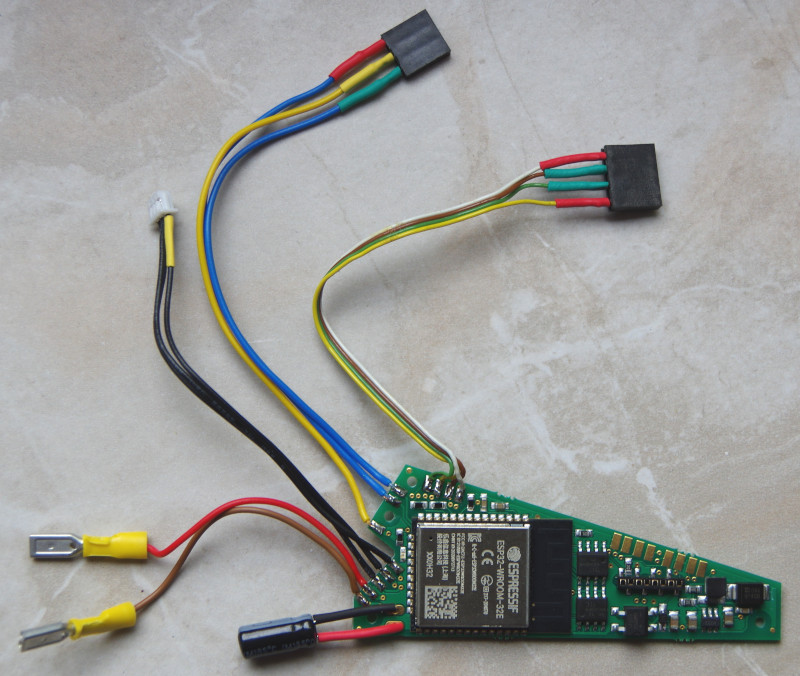
- With one Märklin plug and a socket strip for mounting in a C-Track turnout or C-Track crossing.
- With two Märklin plugs for mounting in a C-Track three-way turnout.
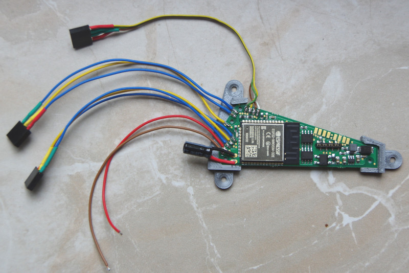
- With two 3-pin socket strips and mounting holder for all other electromagnetic drives with 2 coils.
In the overview “Switching with CTC” you will find more modules and links to installation instructions.
Version with one Märklin plug
This version is intended for installation in Märklin C-Track turnouts. Additionally, another electromagnetic drive with 2 coils each can be connected, e.g. a semaphore signal.

Version with two Märklin plugs
This version is intended for installation in Märklin C-Track three-way turnouts.
Version with two 3-pin socket strips
This version is intended for two electromagnetic drives with 2 coils each. With the included mounting holder, the CTC turnout module can be screwed under the model railway system.

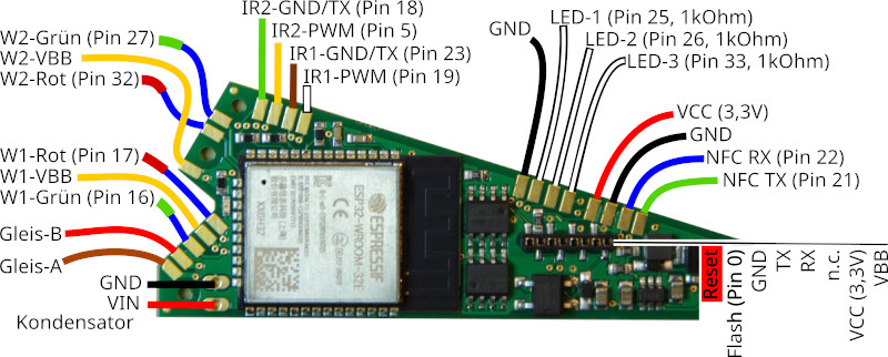
Pin Assignment
The current (second) series has been delivered since July 2021. It can be recognized by the electrolytic capacitor protruding to the side (in the images below left), which allows operation with AC and unsmoothed DC. The wiring always corresponds to one of the three versions mentioned above.

Connection
Notes:
- When choosing the input voltage, please bear in mind that motors, lamps, … connected to the CTC module must also withstand this voltage!
Standard configuration
- Connect the contacts Track-A and Track-B with the track or the power supply. It does not matter whether it is a digital center or a power supply unit, as long as the maximum voltage of 24 V is not exceeded. Since a rectifier is connected at the input, it also does not matter which pole you connect to Track-A and Track-B.
- Connect the power supply of the turnout drive (positive pole, yellow cable for Märklin) with W1-VBB or W2-VBB.
- Connect the switching terminals of the turnout drive (negative pole, blue cables with green or red plug for Märklin) with W1-Green and W1-Red or W2-Green and W2-Red.
- Connect the CTC IR balise with IR1-GND (negative pole, green) and IR1-VCC (positive pole, red) or IR2-GND and IR2-VCC. See also the datasheet of the CTC IR balise. Please do not forget the resistor (typically 1 kOhm, min. 330 Ohm) in the IR balise, otherwise the turnout module will be damaged.
- Connect the NFC Reader to NFC RX, NFC TX as well as GND and VCC. Please note that the second IR balise and the NFC reader cannot be used simultaneously.
- Connect LEDs to one of the terminals LED-1 to LED-3 and GND respectively. When connecting a light signal, if necessary, remove resistors there, as LED-1 to LED-3 already have a 1 kOhm resistor each and switch to 3.3 volts.
The assignment of the pins for switching can be configured in the app (Cfg.xml), as well as the duration of the switching pulse.
Additional Connections
- Connections LED-1 to LED-3 already have appropriate resistors (1 kOhm) on the board so that LEDs can be connected directly (without a series resistor).
NOTE: Without a buffer capacitor, this (old) module is only suitable for operation with switching power supplies!
Archive
Pin Assignment First Series
The first series was delivered until June 2021. The wiring was still discussed individually with each customer.

Notes:
- The LED connection is parallel to the LED on the board and may be loaded with max. 12mA in total (the LED has a 150 Ohm resistor)
- By adapting the ioCfg.xml, the I2C connections can be used for an NFC reader with the current firmware - contact us if needed.


