This article series describes the configuration of automation using the example of a garden railway. It begins with the placement of the NFC balises and ends with full automation via a schedule.
In the first part, we plan the subdivision of the model railway into blocks. Then we place the balises on the track layout.
Note: The functionalities described here require at least CTC App Version 4.04 and associated firmware.
Planning: Blocks and Balises
In Chapter 7.1 - Automation: Blocks of the user manual, there is an introduction to blocks.
We divide the entire track layout of our model railway into individual blocks (track sections). Turnouts (branches) may only exist between blocks, never within a block.
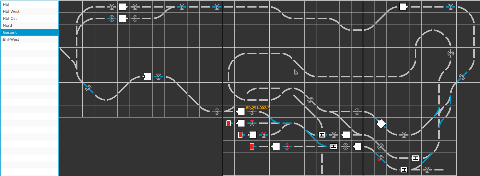
The main part of our garden railway looks as follows. The track leading to the staging yard in the garage via multiple helixes is not included here.

We assign a capital letter to each station. Our layout has three stations which receive the letters “S,” “T,” and “U.”
Within the station, we number the tracks starting with the main tracks, followed by the sidings. After the digits 1 to 9, we use lowercase letters from a to z if necessary. Our station “S” has tracks 1 to 3 for passenger traffic and sidings 4 to 6.
Blocks between stations begin with the letter of the nearest station followed by another capital letter.
The balises within a block are numbered clockwise. Track 1 of our main station “S” has two balises, which thus receive the position IDs “S11” and “S12.”
Each siding receives at least one balise before the bumper, so that a locomotive reading this balise can stop in time before the bumper. On a long siding, we place another balise near the turnout, so that a locomotive stopping over this balise is already fully within the siding.
A balise is also placed before each signal or stop sign, so that a locomotive with the NFC reader stopping over this balise has enough distance to the signal. At a sufficient distance before this balise, another balise is placed to announce the signal to an arriving locomotive, so that it reaches its minimum speed just before the second balise and then stops exactly over the second balise.
Signals or signs don’t necessarily have to be visibly present on the model railway. They can also be present only in the track layout and still be used for train control. Only the balises must physically exist.
Placing NFC Balises
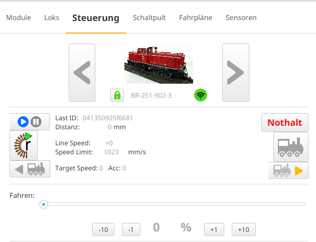
After we have placed all the balises at the planned spots on the track, we drive over the closest balise with the NFC reader of a locomotive. Directly under the image of the locomotive, the unique number of the NFC balise appears next to “Last ID”:

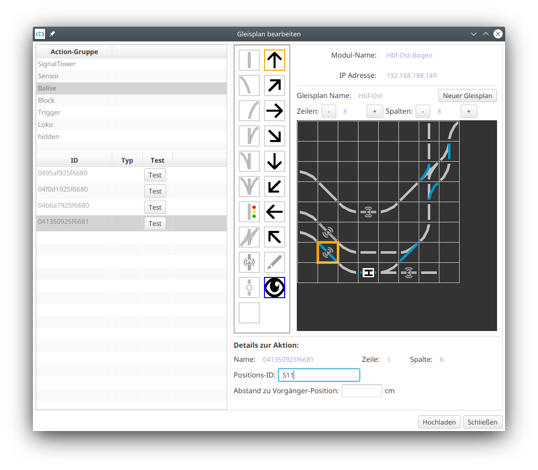
Then we open the track plan where we want to place the balise. There we click on the action group Balise and mark the NFC balise just read by the locomotive in the list below. It should usually be the last one in the list. Then we click on the spot in the track layout where we want to place the balise. The spot is marked with an orange rectangle and the track section turns blue:

Finally, we enter the three-digit position ID into the (here blue-framed) input field.
These steps can be repeated for several NFC balises at once. We can keep the track plan open while we drive the locomotive to the next balise.
When we are finished with the balises of this track plan, we click on “Upload.”
| Part 1 | Continue with Part 2 | Proceed to Part 3 | Proceed to Part 4 | Proceed to Part 5 |
- Categories:
- Automatisierung (8)


