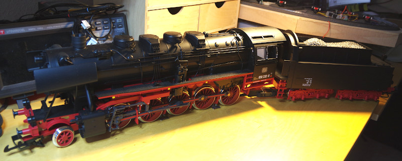
This conversion is about a current model from Piko with a DCC decoder and sound module. In order to enjoy the sound with CTC as well, the CTC-Locomotive module-G is installed between the track and the DCC decoder.
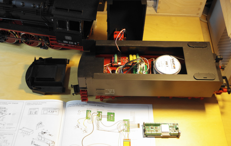
The installation of the DCC decoder is described on pages 12 and 13 of the PIKO BR 50 manual. Although ours is already installed, we now know it is located in the tender and how to disassemble the tender. The following image shows the opened tender in the original PIKO state:
The CTC module is quickly installed:
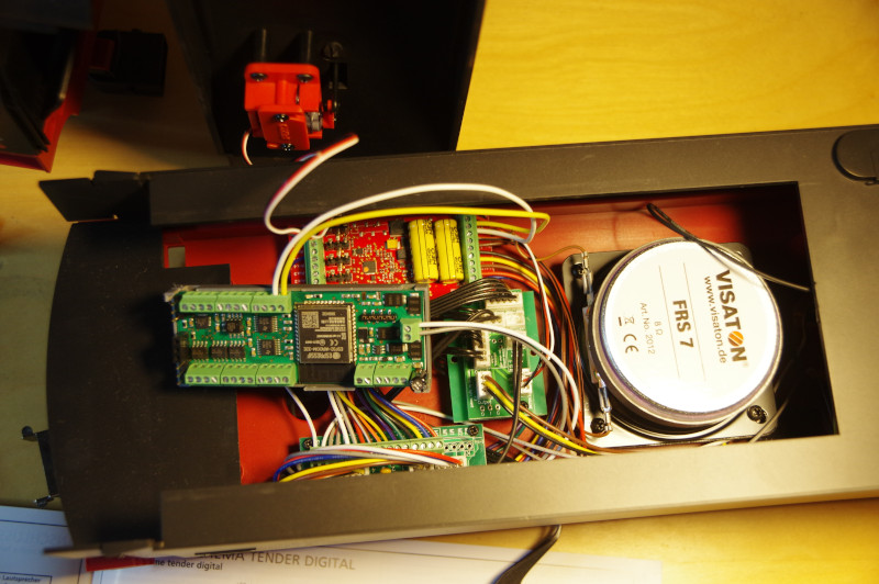
- We disconnect the two wires (white and black) of the track connection from the DCC decoder and connect them to the CTC-Locomotive module (Track-A and Track-B).
- Using two new wires (here white and yellow), we connect the DCC decoder (track connection) to the Motor-1 output of the CTC-Locomotive module.
- Since I am too curious to see if the locomotive works, I will postpone the connection of the NFC reader for another time. I think I will mount it on the front axle suspension of the locomotive.
The following image shows the fully installed CTC-Locomotive module-G:
To be able to operate the locomotive, the configuration of the installed CTC-Locomotive module needs to be adjusted. We do not even have to connect the tender and locomotive: It is sufficient to place the tender on a track with power supply. To test the DCC functionality later, however, the locomotive and tender must be reconnected.
If not already done, we book the CTC-Locomotive module into the model railway WLAN.
Then we open the configuration dialog:
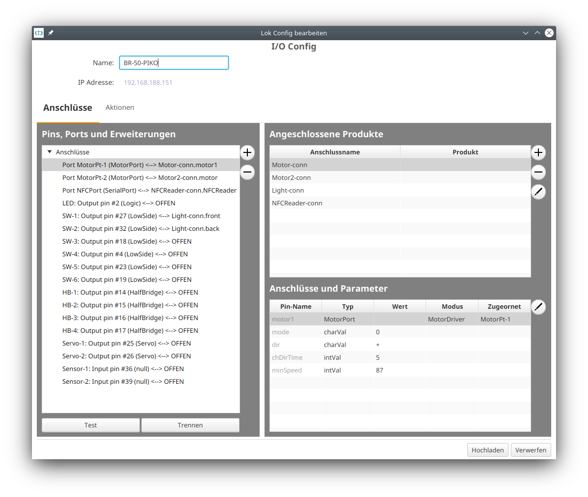
We remove the two pre-configured motors and the light by marking them on the right under “Connected Products” and then clicking the minus button. We leave the pre-configured NFC reader for later installation.
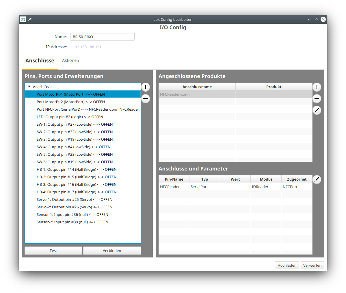
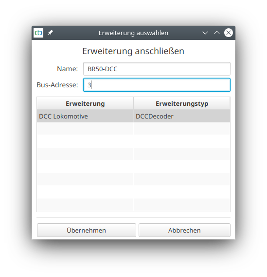
Then we click on the port “Motor-Pt-1” on the left under “Pins, Ports, and Extensions” and then on the plus button next to it. We select the extension catalog “dcc.xml”. There, we select “DCC Locomotive”, give it a name, and enter the DCC address. Note: For brand new DCC locomotives, the address is always set to 3.
Now our config looks as follows:
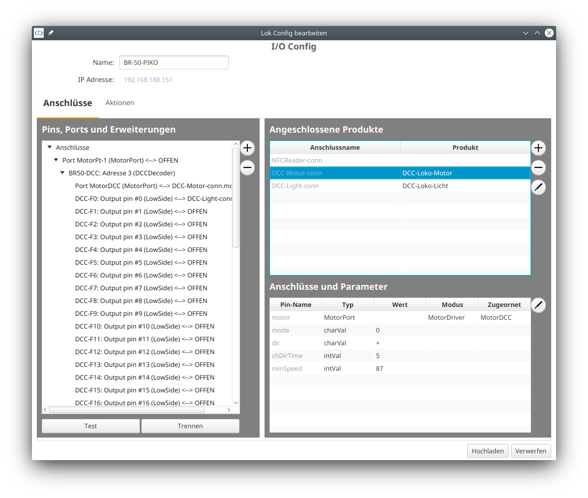
Before we can test, we first need to upload the modified config, and a restart of the CTC app is also recommended.
After the restart, we can already drive the locomotive. For the multitude of DCC functions, we have to go into the configuration dialog again. There, we can test the 28 DCC functions, for example, the steam whistle sounds with DCC-F2.
Using the info sheet of the DCC decoder, we can now set up the functions. To do this, we select the appropriate products from the “universell-loks.xml” product catalog of the CTC app, see also user manual “Connect Products”.
Note: We need at least firmware 20210702 to add all sounds of the BR50. Older firmware crashes with around 10 sounds!
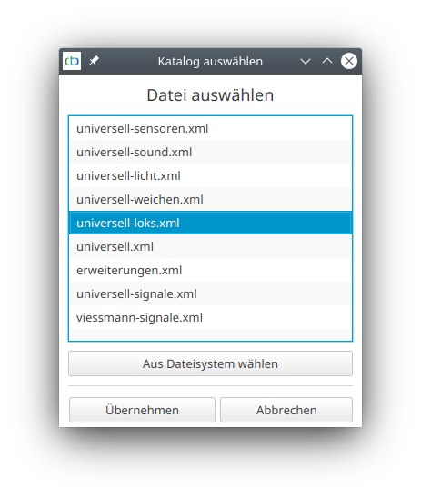
From the catalog, we select Locomotive Sound and give it an appropriate name:
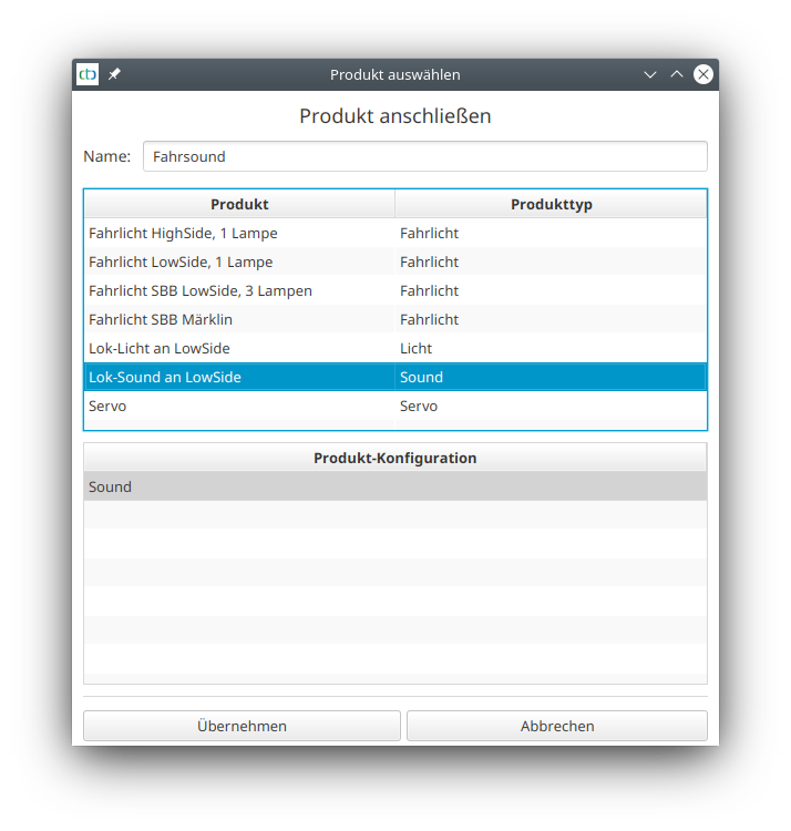
After completing this for all sounds, our config looks as follows:
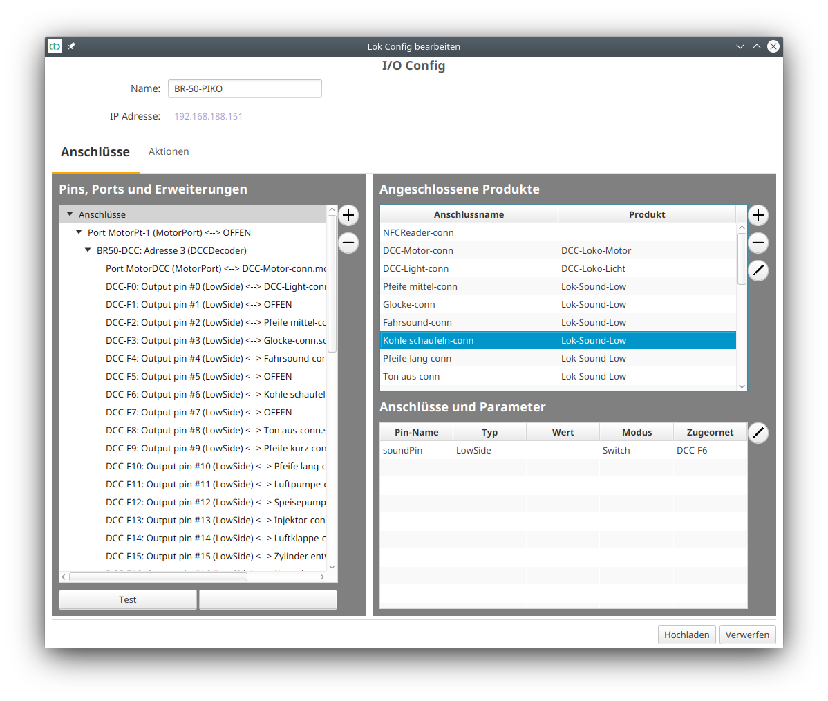
With so many sounds, it is a good idea to combine sounds like the various long whistles into one function so that they appear in one row in the app. Technically, this is no problem, but a suitable entry in the product catalog is still missing.
Connecting NFC Reader (Supplement from 19.09.2021)
There are two possible positions for installing the NFC reader:
- Right behind the first axle
- Rotated 45° under one of the tender bogies
Since wiring to the front axle was too laborious for me, I decided to mount it under the tender. Luckily, there are two holes spaced exactly right for the mounting holes of the NFC reader and also suitable for the available 2.2 x 16mm sheet metal screws. With an 8 mm spacer and the provided packaging of the NFC reader from CTC, the result looks as follows:
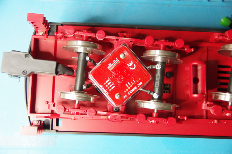
The NFC reader is almost completely hidden by the frame of the bogie.
The hole above the bogie, through which the power cables from the axles are also routed, still offers enough space for the connection cables of the NFC reader. These are connected to the designated contacts of the CTC-Locomotive module-G:
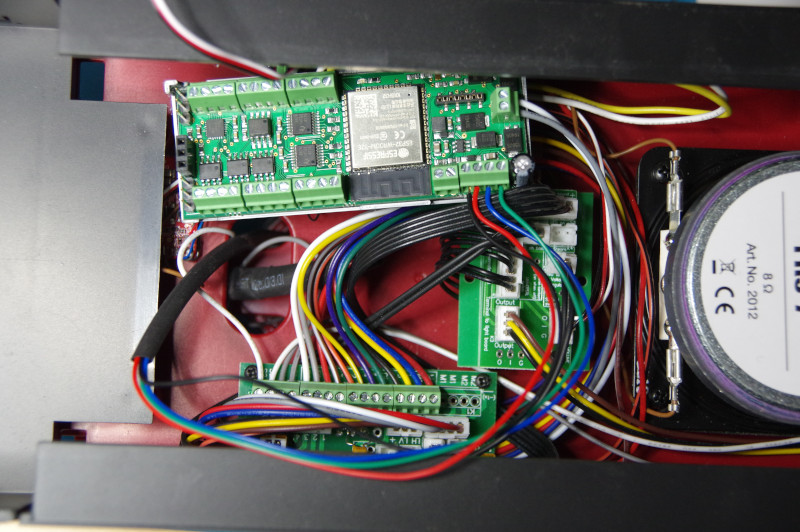
There is nothing to configure: An NFC reader is pre-configured in the CTC-Locomotive module-G.
- Categories:
- CTC-Module (10) ,
- Umsteigen (7) ,
- DCC (1)


