To be able to switch a turnout within the framework of a CTC-controlled railway, it must be connected to a CTC turnout module or a CTC IO module. In the following example, a Märklin C-Track turnout is used. It has two magnetic coils as a drive. The drive of a turnout with servomotors is not considered here.
Important: This documentation was created prior to our decision on cable colors. The cable colors in the photos do not correspond to this decision!
The datasheet of the CTC turnout module can be found here: CTC Turnout Module. When ordering a CTC turnout module, it is necessary to specify which functions of the CTC turnout module are used. This allows the corresponding wiring to be soldered at the factory to the CTC turnout module.
Possible factory connections are specified in the datasheet:
- Track-A, Track-B: Power supply. Here, when using Märklin C-Tracks, a cable with configured connectors is attached, which is plugged into the track connections.
- W1-Green, W1-VBB, W1-Red: Control of the turnout’s magnetic coils. Here, when using Märklin C-Tracks, a cable with a configured connector is attached, so that only the connector needs to be plugged into the turnout drive.
- W2-Green, W2-VBB, W2-Red: Control of the magnetic coils of an optional second turnout or a second turnout drive, such as in a three-way turnout. Here, when using Märklin C-Tracks with a three-way turnout, a cable with a configured connector is attached, so that only the connector needs to be plugged into the turnout drive. These connections can also operate the magnetic coils of a signal, as is the case with the starter set.
- IR1-GND, IR1-Vcc, IR2-GND, IR2-Vcc: Control of infrared emitting diodes. IRx-GND is connected to the cathode and IRx-Vcc to the anode.
The factory-soldered cables must not be subjected to any mechanical stress, otherwise the solder connections on the board will come loose!
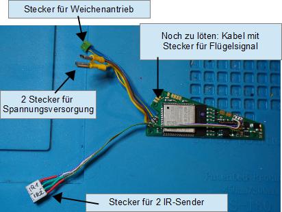
The following image shows a module shortly before installation into a Märklin C-Track turnout. It is wired as follows:
- 2 connectors for power supply. These are plugged directly into the Märklin C-Track.
- Connector for turnout drive. This connector is plugged directly into the turnout drive.
- Connector for 2 IR balises. 2 IR balises can be connected here, pay attention to color coding!
- Yet to be soldered: Cable with connector for semaphore signal. In the case of the starter set, a semaphore signal is connected here. Alternatively, a second turnout drive can also be connected.
Further installation notes:
- The Märklin turnout already has prefabricated small plastic nipples as assembly aids.
- The CTC turnout module has corresponding holes for the plastic nipples.
- The CTC turnout module is provided with insulating tape in certain areas to prevent short circuits with the metal parts of the turnout.
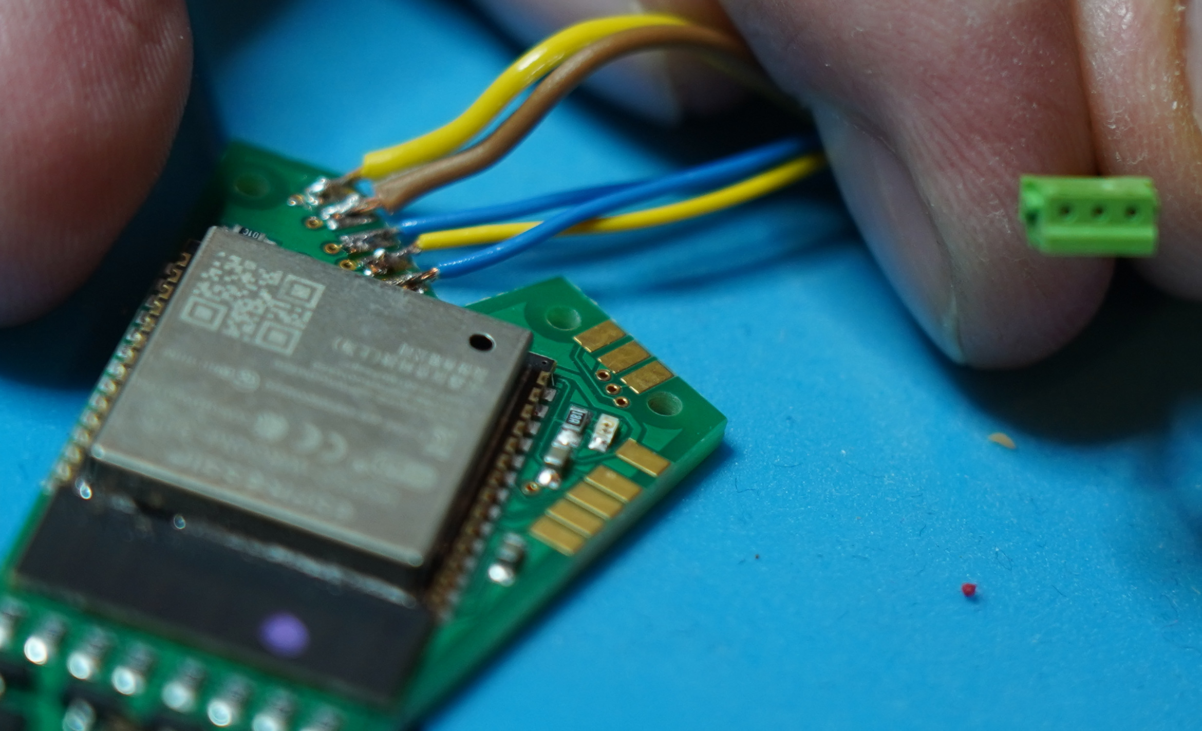
Regarding the plug connection of the CTC turnout module for the turnout drive, it should be noted that the plug in the socket is mechanically foolproof. Caution is required because it is a relatively small plug and can be inserted the wrong way with “brute force”. The image shows a section of the CTC turnout module and the plug for the Märklin C-Track turnout.
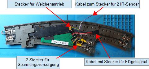
The CTC turnout module is inserted into the designated place from below into the turnout. The 2 power supply plugs and the turnout drive plug as well. See Fig. 3: Turnout_with_labeled_turnout_module.jpg. Once the turnout is installed in the track system or the power supply is connected separately, the configuration of the CTC turnout module can begin.
The configuration of a CTC turnout module is described in Chapter 4.1 of the manual.
Installation images second series
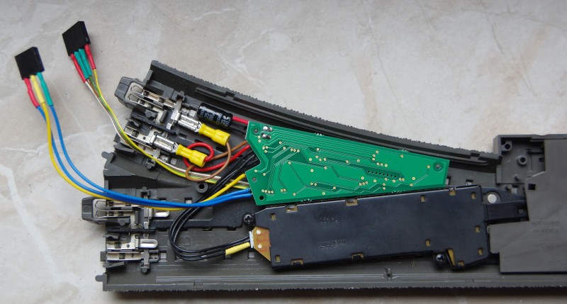
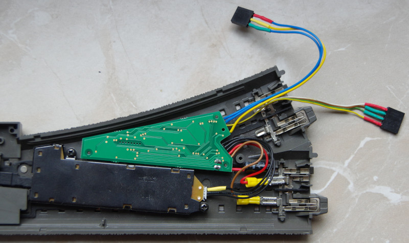
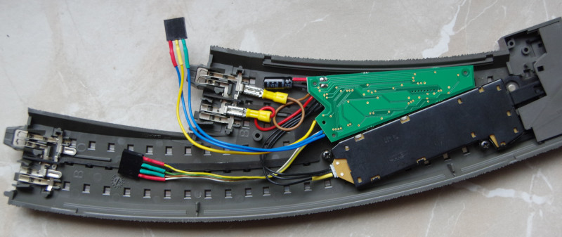
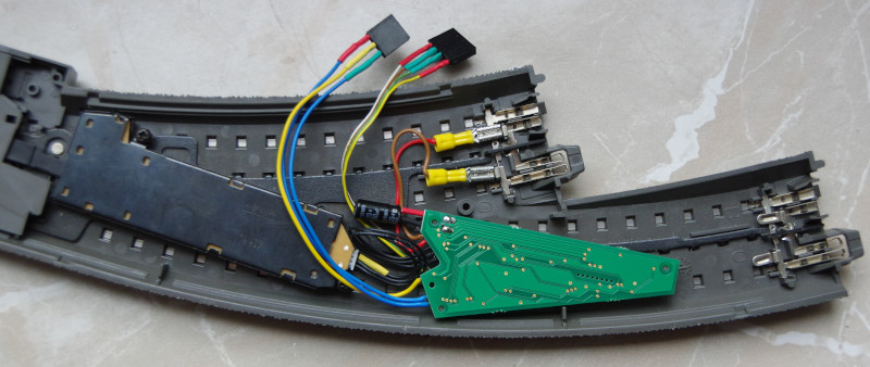
The following images show the installation of the second series of the CTC turnout module, delivered from July 2021, into the various C-Track turnouts:
- Categories:
- CTC-Module (10) ,
- Umsteigen (7)


