In this article, I will show you how to equip the Piko G turnout drive (No.35271) including the turnout lantern (No. 35266) with a CTC turnout module G.
Important: This documentation was created before our decision regarding cable colors. The cable colors in the photos do not correspond to this decision!
First, here is the fully converted turnout drive:
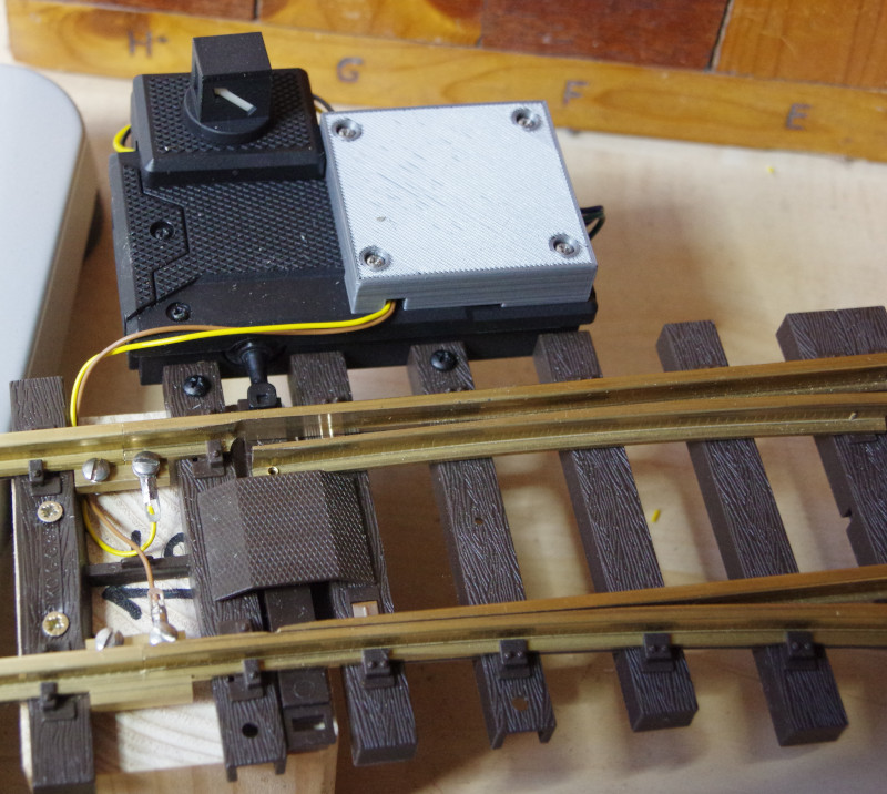
You will of course receive the cover from us in black. For this guide, I used the gray prototype.
First, the turnout lantern is attached according to the instructions included with the product. At the end of the connecting cables of the turnout lantern, there are a diode and a resistor just before the plug. The purpose of the diode is unclear to me. The resistor is essential because the lantern contains an LED that would burn out without the resistor. When shortening the cables, we must therefore keep the resistor, which in my case was in the black cable.
Before we connect the turnout lantern, we take care of the turnout drive. To do this, the two short cables (green and blue, about 4.5 cm long) are pushed through the designated holes and screwed from above. Then we pull firmly on both cables to ensure that we have screwed them in well. I had also removed the cover of the seal, which turned out to be unnecessary:
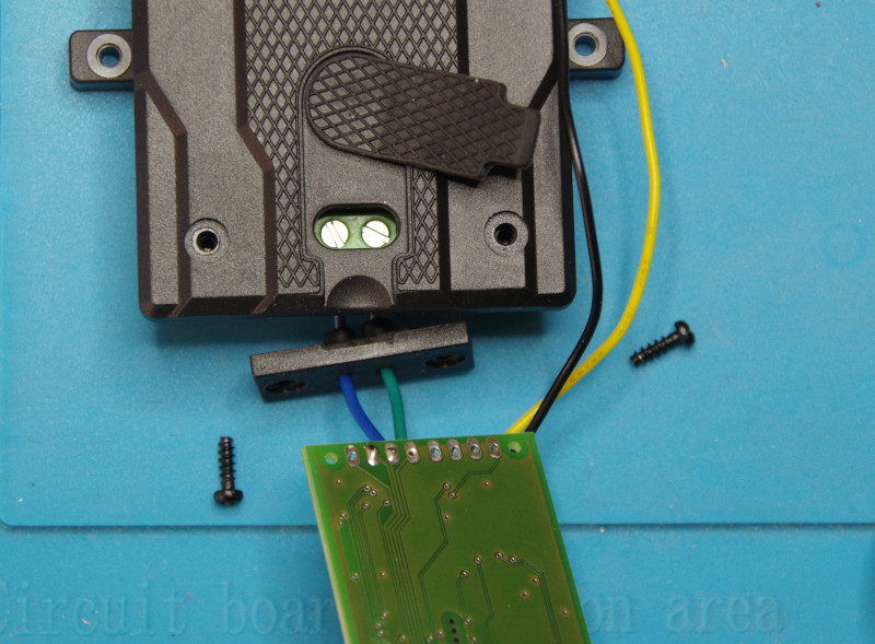
Why Piko uses a black cable for the positive pole, which is usually used for the negative pole, is a mystery to me? We connect the positive pole of the turnout lantern (black cable with resistor) to the HB-3 output and the negative pole to GND of the CTC turnout module G. In the following picture, the CTC turnout module G is fully wired, and the cover included in the delivery is already ready on the left.
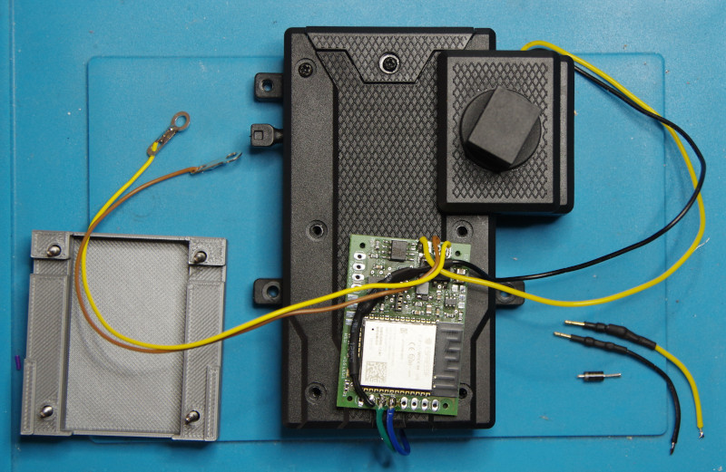
At the latest now, we have to remove the four screws that will later be covered by the lid. They are replaced by correspondingly longer screws, which are also supplied. We now insert the CTC turnout module G into the lid and guide the cables through the designated recesses:
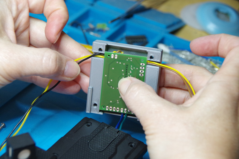
Then we place the lid on the housing of the turnout drive and carefully fold it down. Here, we must pay particular attention to ensuring that the cables remain in their recesses:
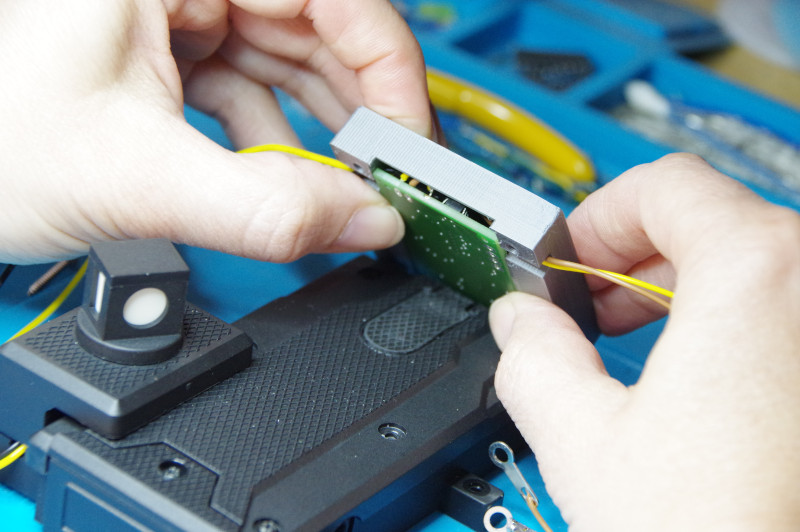
Finally, we slide the lid into position:
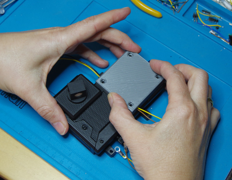
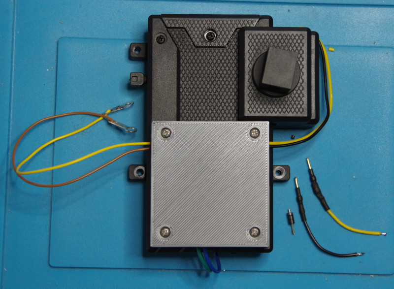
Then gently screw in the four screws (plastic threads!) and finish. On the right side of the picture, you can see the remaining cable ends and the diode of the turnout lantern.
- Categories:
- CTC-Module (10) ,
- Umsteigen (8)


