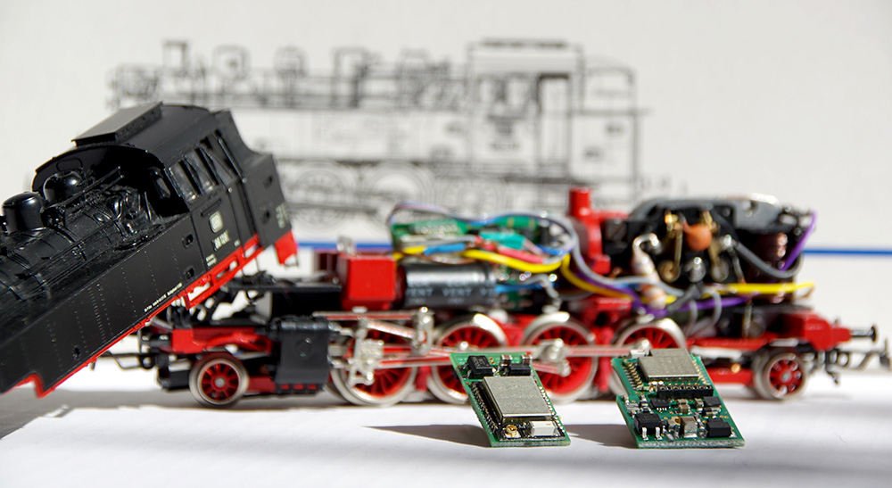
As with digital decoders, there is no single universal locomotive module for CTC either. The internal connections and space constraints of locomotives vary too widely.
Common Features of All CTC Locomotive Modules
| Feature | Description |
|---|---|
| Input Voltage | approx. 9 V to 24 V DC, digital current or AC (with backup capacitor) |
| Interfaces | CTC-IR-Receiver, I2C or CTC-NFC-Reader |
From February 2025, we will include a TVS diode with all G-scale locomotive modules. For smaller scales, it should be sufficient to install TVS diodes in the track. See the “Overvoltage Protection” section on the “Power Supply and Router” page.
Overview of CTC Locomotive Modules
| CTC Locomotive Module | Optimized for | Dimensions | Motor Output | Switching Outputs | Sound Socket | Max. Total Current |
|---|---|---|---|---|---|---|
| CTC-Lokmodul-M3 | PluX22 | 30 x 15.5 mm | 1x 1.0 A | 8 half-bridges | SUSI3 | 2 A |
| 21mtc (Märklin) | 30 x 15.5 mm | 1x 1.0 A | 6 half-bridges + 2 digital | SUSI3 | 2 A | |
| NEM-652 (8-pin) | 30 x 15.5 mm | 1x 1.0 A | 3 half-bridges (2x light, AUX) | SUSI3 | 2 A | |
| NEM-651 (6-pin) | 30 x 15.5 mm | 1x 1.0 A | 2 half-bridges (2x light) | SUSI3 | 2 A | |
| Cable, 2 to 6 AUX | 30 x 15.5 mm | 1x 1.0 A | 4 to 8 half-bridges | SUSI3 | 2 A | |
| DCC | 30 x 15.5 mm | DCC total 1.0 A | - | SUSI3 | 2 A | |
| CTC-Lokmodul-21mtc (remaining stock) | 21mtc (Märklin) | 30 x 15.5 mm | 1x 1.0 A | 6 LowSide + 2 digital | - | 2 A |
| CTC-Lokmodul-PluX22 (remaining stock) | PluX22 | 30 x 16 mm | 1x 1.0 A | 8 LowSide or 8 half-bridges | via train bus | 2 A |
| CTC-Lokmodul-G2 | LGB / large scales | 78 x 30 mm | 2x 1.0 A or 2x 2.0 A | 6x 1.2 A LowSide 4x 2.5 A half-bridge |
SUSI3 | 15 A |
Discontinued locomotive modules:
Notes:
- Operating CTC locomotive modules on alternating current (AC) or unfiltered direct current without a smoothing capacitor will cause irreversible damage to the CTC module.
- Switching outputs are differentiated based on whether they switch ground/negative (LowSide) or the positive pole (HighSide). Especially with LED boards at the front, there is often a common line for one pole. It is then important whether the switching outputs of the locomotive module are designed as HighSide or LowSide.
- A half-bridge can switch between the positive and negative poles but is never fully off. Particularly so-called magnetic accessories (e.g., uncouplers) can be permanently damaged if connected to a half-bridge with incorrect configuration and should therefore not be connected to a half-bridge.
- An additional module is required for powering servos.
- If consumers (lamps, smoke generators, etc.) in the locomotive have a connection to the housing, they may only be connected to the CTC module via a protective diode.
Locomotive Conversion
On the Locomotive Conversion page, you will find general information about locomotive conversions as well as various documented conversions in text and images. These are updated regularly.


