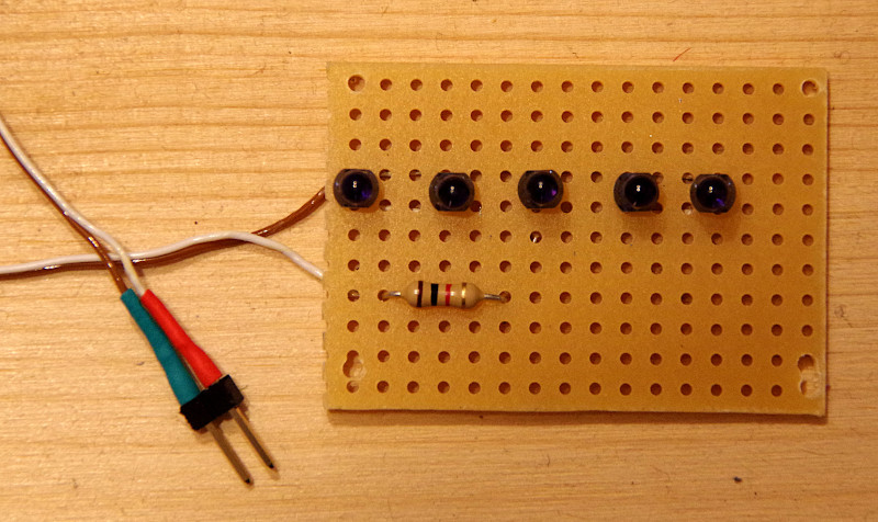
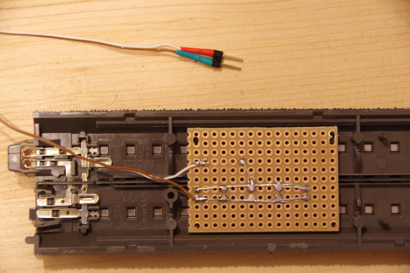
IR balises are infrared light-emitting diodes with a wavelength of 950 nm. Several are connected in parallel for an IR balise and equipped with a ballast resistor so that they only send a few centimeters. The ballast resistor must be designed in such a way that a maximum of 10mA current flows at 3.3V.
As we are still experimenting with the design, we cannot offer any finished transmitters at the moment.
Our kit for the Märklin C-Track currently contains five IR LEDs with a 950nm wavelength (e.g. Vishay TSUS 4300) and a 1 kOhm ballast resistor.
Note: We recommend NFC instead of IR for use with garden railways, see CTC-NFC-Reader
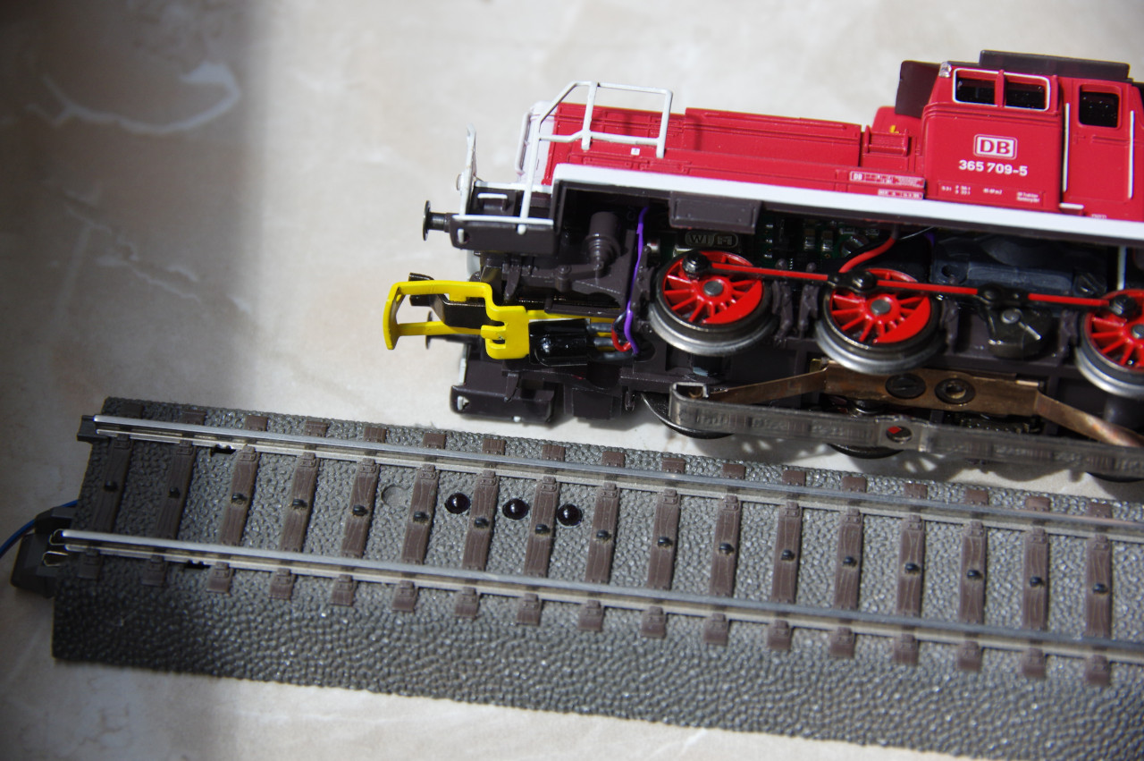
For our locomotive modules, the IR receiver is available together with a cable and suitable mini plug. To ease installation, the IR receiver is supplied separately and must be soldered by you. In the picture above, the IR receiver (black box) was glued under the front coupling (yellow).
IR-Balise Kit for C-Track
The following picture shows the still unprocessed C-track and the parts of the IR-balise kit:
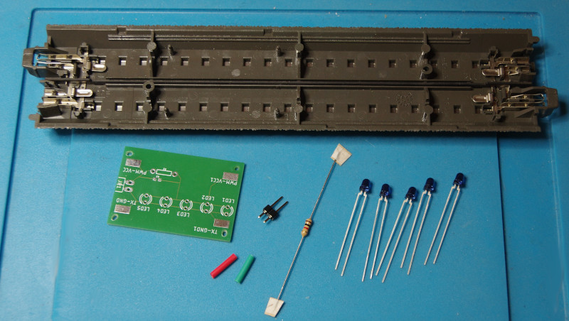
The following steps are needed to self-assemble the IR-balise:
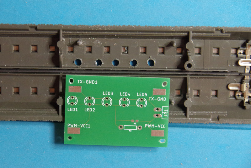
- Use the board to measure and drill 5 holes in the track (3 mm in diameter), where the mounting pins are located under the track:
- Insert the IR LEDs into the designated holes of the board (long leg towards the center of the track) and then insert both into the C-track.
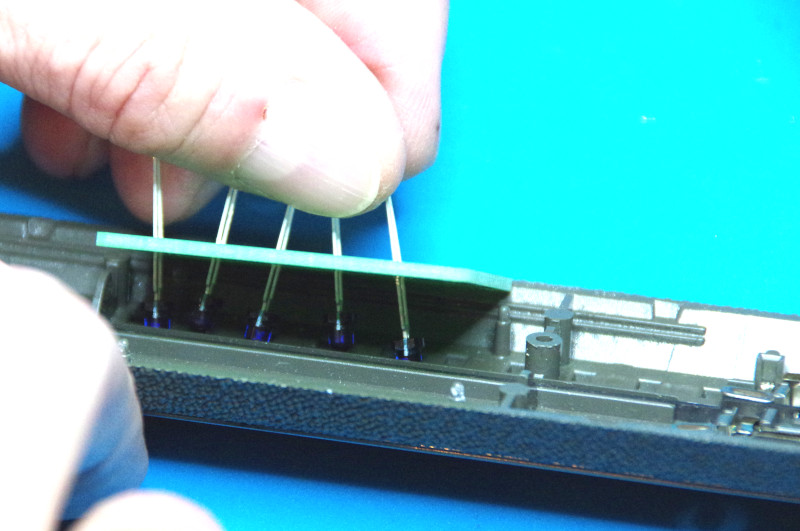
- Only now solder the IR LEDs.
- Remove the board, insert the resistor, and solder it.
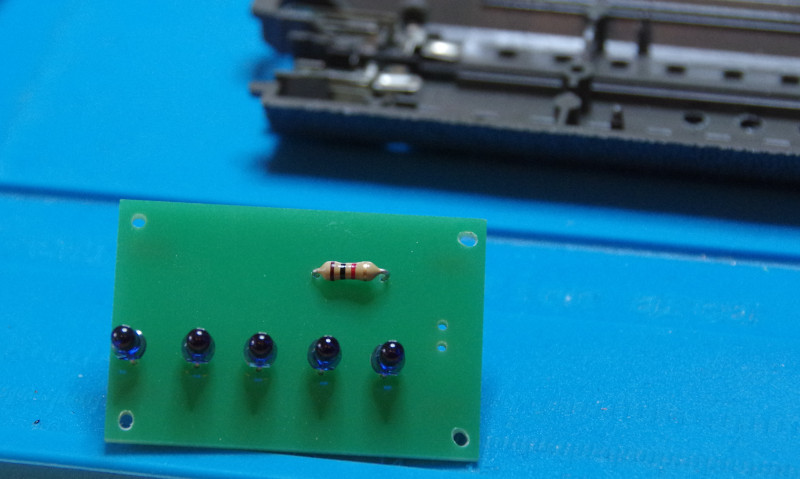
- Reinsert the board and solder connection wires and plug:
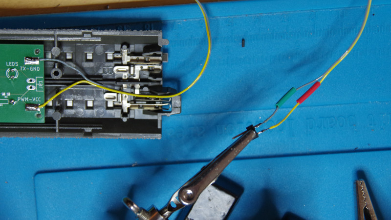 The positive pole (in the picture yellow cable, red heat shrink) goes to PWM-VCC and the negative pole (in the picture gray cable, green heat shrink) to TX-GND.
 - You can determine whether all the IR LEDs are working with your phone’s camera.
For this, connect the IR balise to about 16V DC voltage (red heat shrink to the positive pole).
In the camera app of your phone, you should now see the LEDs shimmering purple (possibly shield some ambient light):
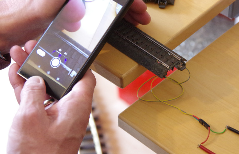 As the LEDs only radiate at a rather sharp angle upwards, you may need to move the phone around a little to check all LEDs.
If the IR balises are connected to the CTC module (3.3 V), unfortunately the phone’s camera will not see anything anymore.
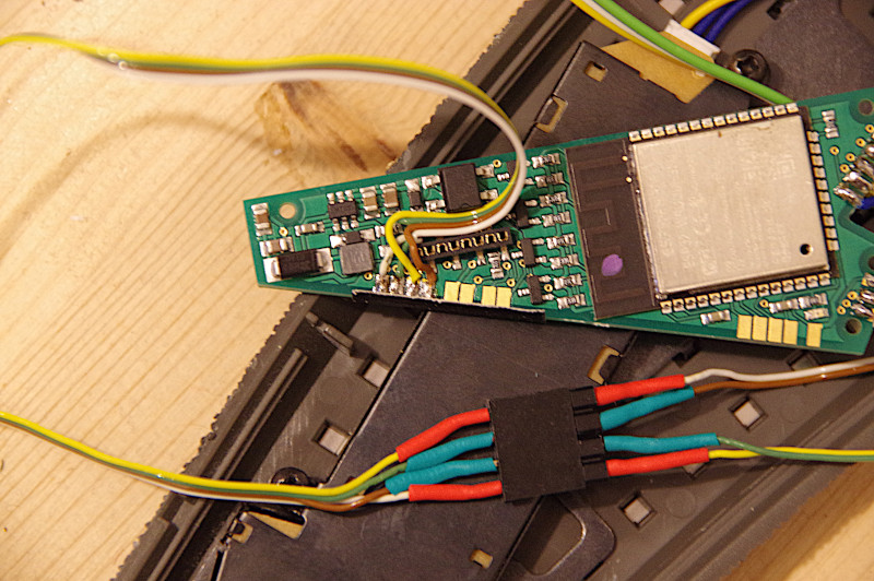
 - The only thing left now is the connection to a CTC turnout module or the CTC-IO-Board.
The plug on the CTC module is marked with heat shrinks in the same colors (red, green):
IR-balise for the C-track without a kit
Of course, you can also create an IR-balise without using our kit, as the previous tutorial has shown. We use Vishay TSUS 4300 LEDs (wavelength 950 nm) and the resistance is 1 kOhm.
