Note: This article was updated on 05.02.2021 to match the new version 3 of CTC. Screenshots that have only changed visually have been retained.
In this article, I will show you how a CTC model railway is created. We will cover everything that CTC involves: From CTC-locomotive and CTC-turnout modules to infrared sensors and simple automation. The only thing we will neglect is the model landscape.
Planning and Parts List
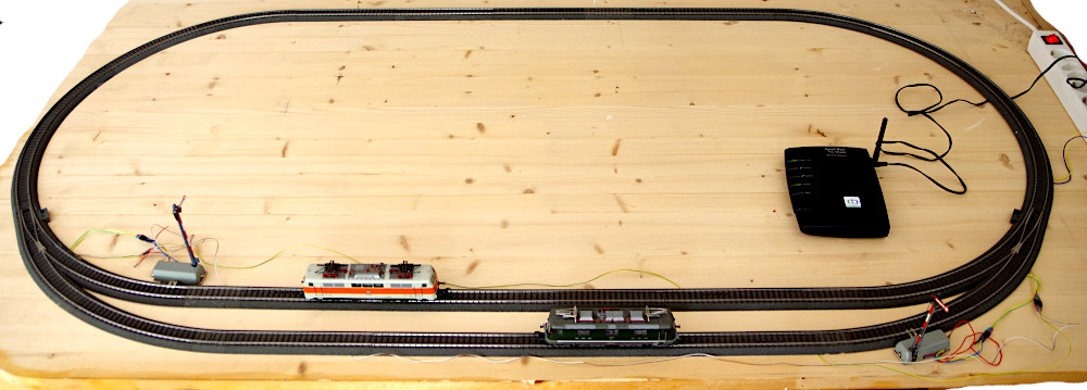
Our model railway will be a simple oval track with a passing loop. We use Märklin C-tracks (H0 scale) because I’m most familiar with them as an old Märklin enthusiast. However, there’s nothing to prevent you from building this demo layout based on a two-rail system. Due to the size of the locomotive modules, it is not yet possible to go smaller than TT scale.
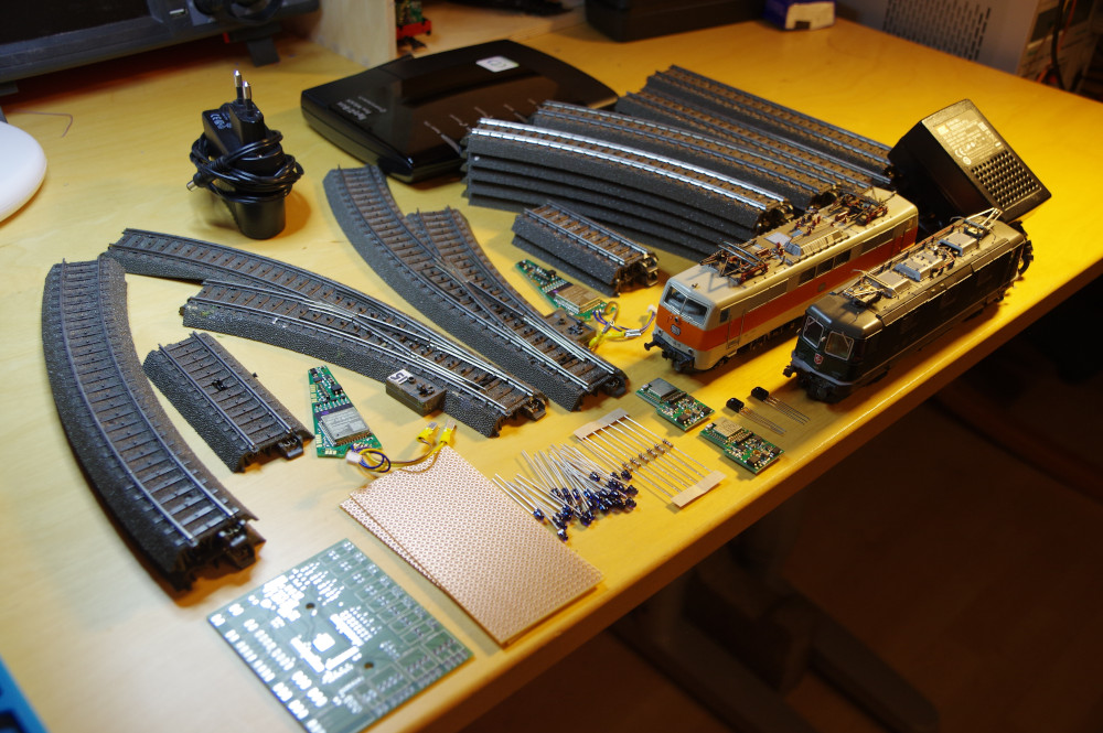
Note: The photo already shows some components that we will only need for the second part.
Here’s what we need for the model railway itself:
- 10x curved track R1, 30°
- 2x curved track R2, 30°
- 12x straight track 188.3 mm
- 4x straight track 77.5 mm
- 1 pair curved turnouts including electric drive
- 2x semaphore signal
- 2x locomotive
- 1x power supply with connection cable for C-track
Additionally, to make it a CTC model railway, we need:
- 1x CTC Router
- 2x CTC Turnout Module
- 2x CTC Locomotive Module
- 4x CTC IR-Balise: 20x IR-LED, 4x 1 kOhm resistors, 2 perforated boards 50 mm x 100 mm, cables, 6x 2-pin header connector 2.54 mm
- Cables and connectors (2x 3-pin and 2x 4-pin socket connector 2.54 mm) to connect the signals and CTC IR-balises to the CTC turnout modules
Preparation
Installing IR-Balises in the Tracks
How to install the IR-balises in the track can be read in the article CTC IR-Balise.
Modifying Locomotives
The modification of a Märklin E103 has been extensively described by Klaus Gungl here: Locomotive Modification
Supplementing CTC Turnout Modules
To connect our two signals and four of the six IR-balises to our two CTC turnout modules, we need to solder a few more cables to them:
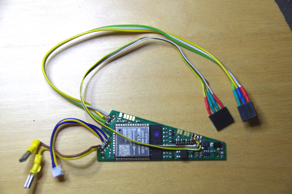
Next, the CTC turnout modules are installed in the two curved turnouts:
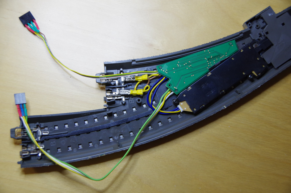
Assembling the Model Railway
Assembling the model railway is quickly done:
-
Plug the power supply into any track.
-
Connect the tracks together.
-
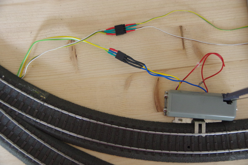
Connect the two IR-balises and the corresponding signal to the CTC turnout modules. In the process, the front track is connected to the CTC module of the right turnout and the rear track to the CTC module of the left turnout.
Configuring the Model Railway
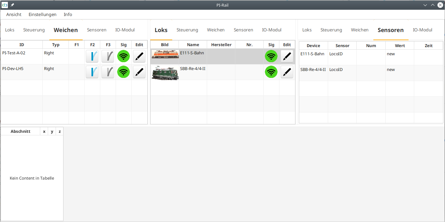
Now, we plug in the CTC router and wait until its Wi-Fi light is on permanently. Then we plug in the model railway and open the app. After a few seconds, the app shows the locomotives and turnouts, but of course, no track diagram yet:
Note 1: Regarding the CTC modules, we assume that you provided us with the credentials of your model railway Wi-Fi when purchasing the modules. If not, you will not yet see any locomotives or turnouts and will need to register them in the model railway Wi-Fi using the CTC app. Instructions on how to do this can be found in the CTC App Documentation.
Note 2: Many of the following steps with the CTC app are also extensively described in the CTC App Documentation.
Configuring CTC Turnout Modules
In this step, we specify that a turnout, a signal, and two IR-balises are connected to each CTC turnout module. All turnouts and signals will be given descriptive names.
To figure out which turnout is installed where, the simplest way is to switch them in the turnout view of the CTC app. Then click the pencil icon next to the turnout to configure it. First, we change the name of the CTC module:
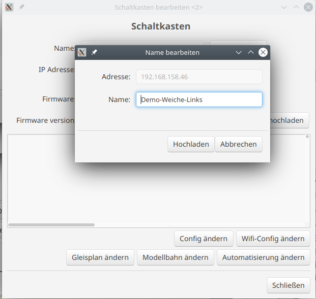
Then we go to the Config:

There, we click the pencil icon next to the turnout and change its name.
Next, we add the signals by selecting them from the product catalog “universell-signale.xml”.
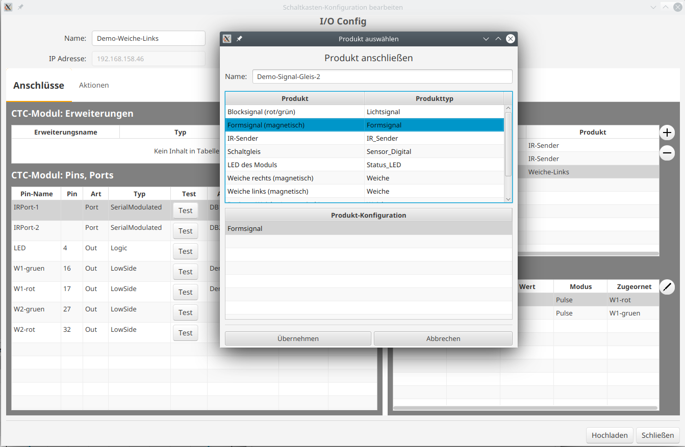
Then, we specify which pins are connected to which signal terminals.
Now the CTC app shows the correct names for the turnouts and, most importantly, the signals.
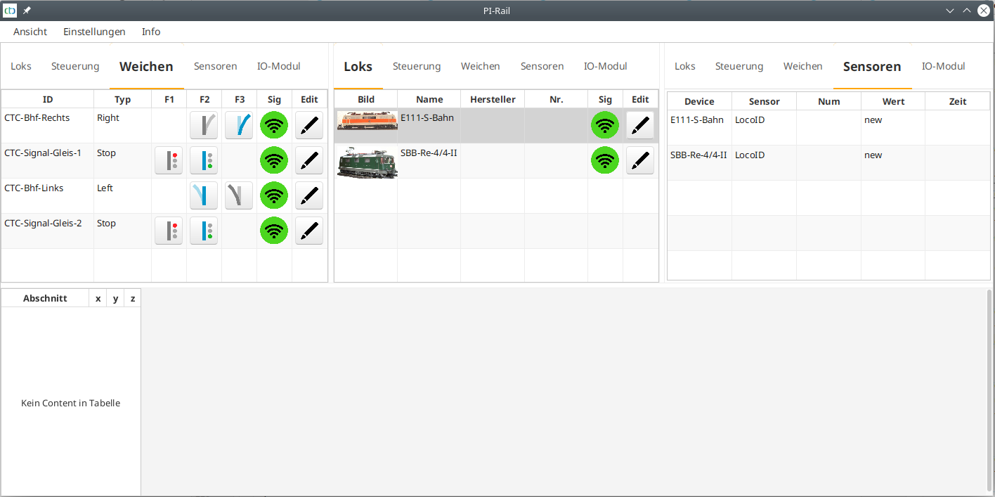
Remaining to test whether signals and turnouts switch in the correct direction. If not, then
- we can most easily reverse the plug 180° for the signals.
- for the turnouts, we need to adjust the pin to be switched in the Config.
The name of the IR-balises consists of two characters for the track section and another for the numbering in a clockwise direction. We also enter the distance in centimeters from the previous IR-balise in the same track section.
Creating a Track Plan
Since we want to make our model railway separable in the middle, we create two track plans. These are stored in the left and right turnouts.
Here’s how a track plan is created:
- Open the configurer in the CTC app and select the CTC turnout module in which the track plan is to be stored.
- Click the “Config” button and then “Change Track Plan”
- Draw the track plan.
- Assign the turnouts, signals, and IR-balises.
- Upload the track plan to the module.
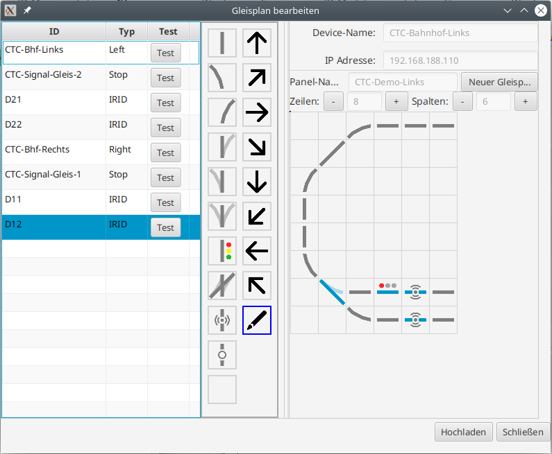
Creating the Model Railway
In this step, the two track plans are combined into one model railway. Only then will they be displayed in the track control panel.
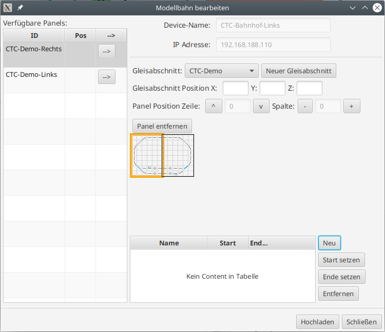
First Test Run
After everything is configured, we start the CTC app again to ensure that everything we see also comes from the CTC modules.
Now we can switch the turnouts and signals and control the locomotives via the track plan.
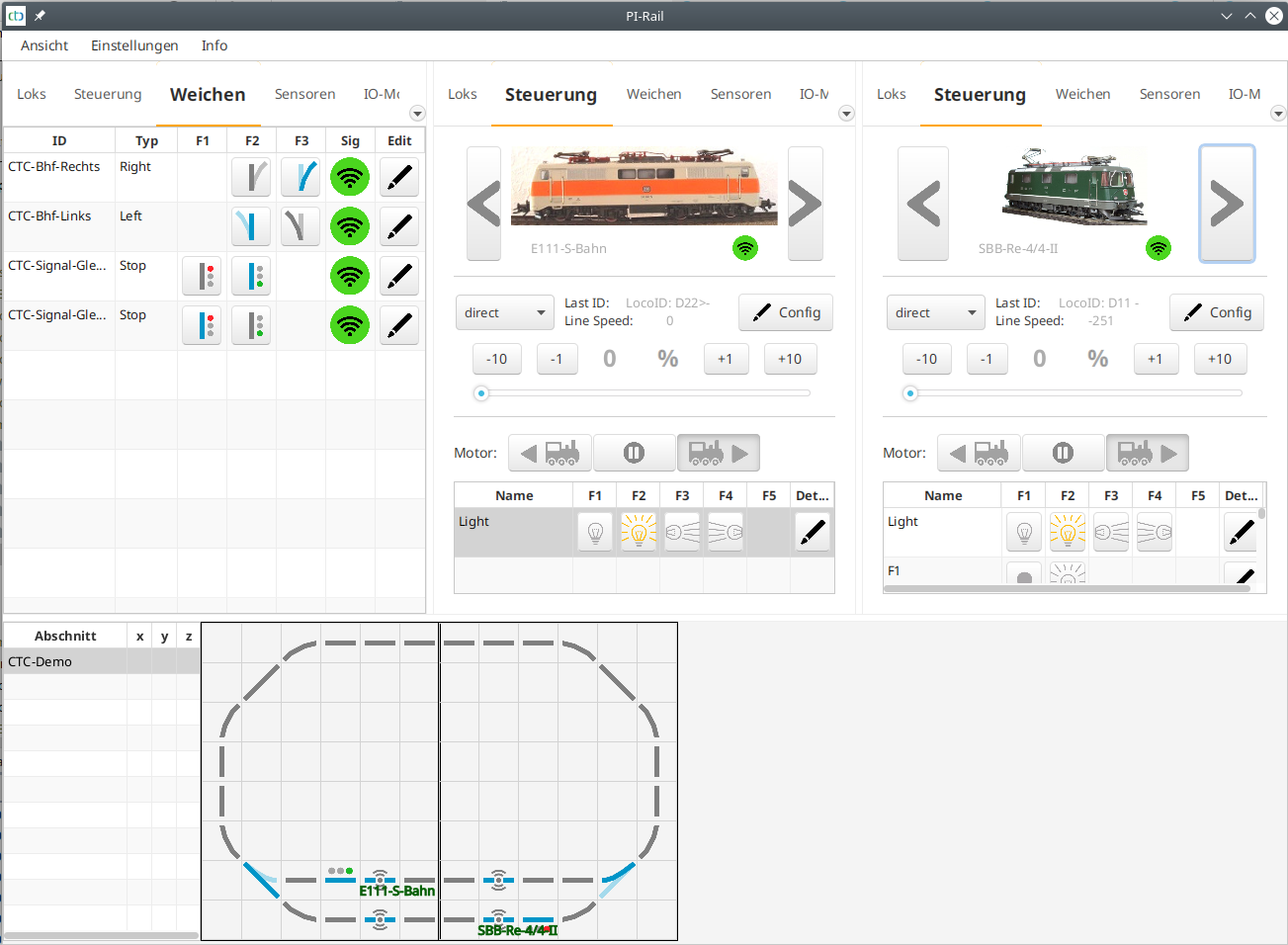
When the locomotive drives over a sensor, it is displayed at the corresponding location on the track plan. We also see the name of the sensor passed in the locomotive’s panel. If the locomotive runs over the second sensor of a track section, the speed of the locomotive between the two sensors is also displayed in cm/s.
Automatic Operation
For automatic operation, we now only need to link the sensors with appropriate commands. Instructions on how to do this can be found in the article Automated Driving
- Categories:
- Modellbahn (3)


