This documentation describes the conversion of a “vintage” H0 locomotive into a locomotive controlled electronically by a smartphone app. By “vintage” H0 locomotive, it means a locomotive that is conventionally controlled analogously. The speed of the locomotive was controlled by the level of the supply voltage applied to the track. In contrast, after the conversion, a constant supply voltage is applied to the track. The electronics developed by CTC will be installed and connected in the locomotive. The necessary control information is sent from the smartphone via WLAN to the CTC electronics, which controls speed, direction, and lighting.
This documentation shows the conversion using a locomotive of the E103 series. In the first step, the locomotive is partially disassembled. Components and wiring that are not needed are removed. In the second step, the CTC electronics are connected and installed in the locomotive. In the third step, the electronics are brought into operation, a connection to the locomotive is established via WLAN from the smartphone, and the functions are tested. At the end of the assembly work, the locomotive is reassembled so that the housing is fully mounted again. The locomotive is then ready for use.
This description assumes that you have the appropriate tools and knowledge. Knowledge of electrical and electronic components is useful. Soldering skills … are good to have.
Important: This documentation was created before our specification regarding cable colors. Therefore, the cable colors in the photos do not correspond to this specification!
Preparatory Work and Workspace
Electronic components are partially sensitive, a workstation equipped with antistatic precautions is recommended.
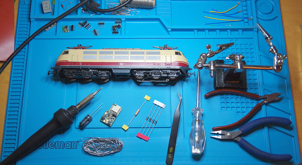
You need the following tools:
- Fine tweezers
- Small side cutters
- Electronics soldering iron (with a thin tip, e.g., 1mm)
- Solder
- Flux
The required components are:
- CTC electronics
- 1 capacitor 1000uF 25V
- 4 diodes
- 1 choke
- Insulated wires
Disassembling the Locomotive
In this step, the housing is removed, and the no longer needed electrical components are removed.
Housing Disassembly
To disassemble the housing, the corresponding housing screws must be loosened. These can be found on the top or bottom of the locomotive, usually a bit hidden so they do not disrupt the external appearance. An exploded view drawing of the locomotive, which you may find on the internet, can be helpful.
In the depicted E103 locomotive, you will find the housing screws on the top of the housing directly at the pantographs for the overhead line.
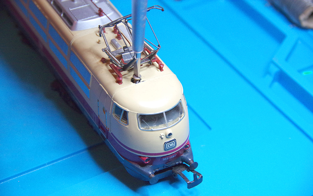
Loosen the housing screws, remove them, and set them aside in a safe place. You can now carefully lift off the upper part of the housing. Be careful not to bend the pantographs and their lead wires inside the housing.
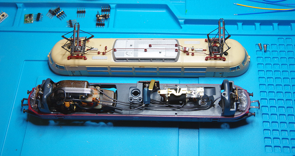
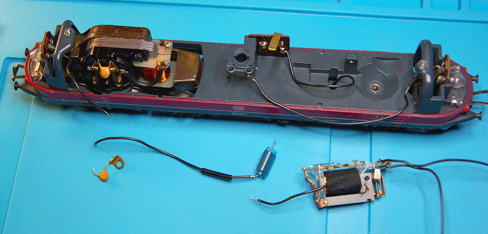
In the picture, you see the upper and lower parts of the housing in front of you. The lower part of the housing carries the running gear with the motor, the direction switch, and the lighting.
In the next step, the unneeded components and wires are removed.
Removing Unneeded Components
The unneeded wires are now removed, and the direction switch is removed.
Looking from above at the lower part of the housing, the motor is on the left, and the direction switch is on the right in the image.
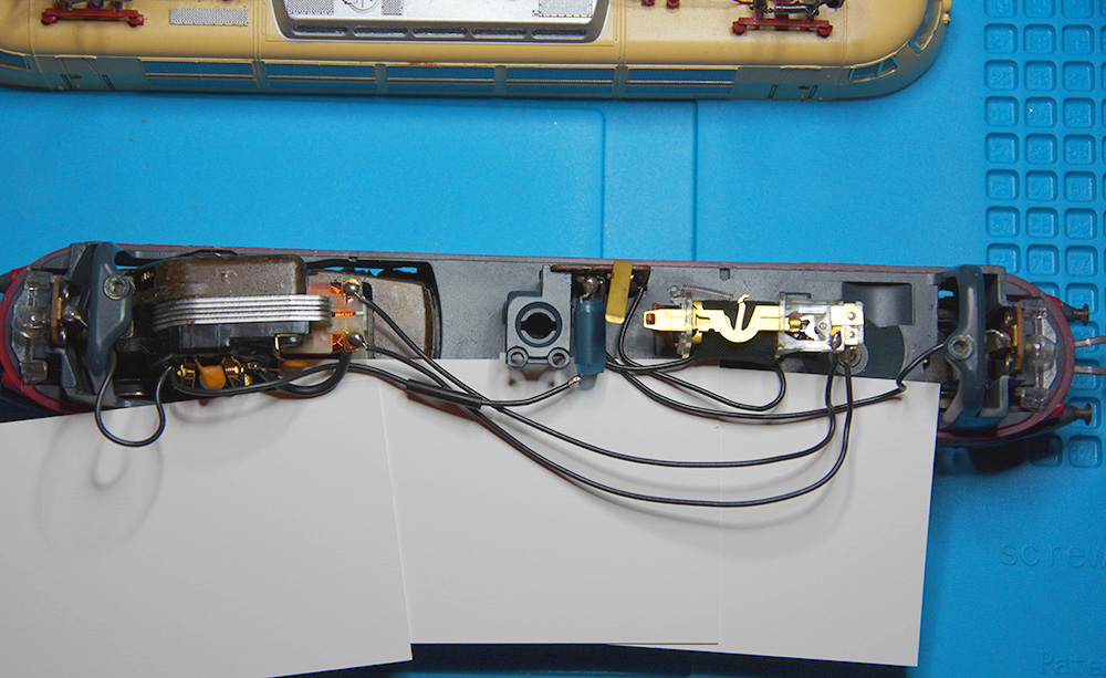
The motor has 3 wires leading to it, 2 of which go to the clearly visible coils of the motor. These 3 wires connect the motor and the direction switch. Loosen the mounting screw of the direction switch and remove it from the holder.
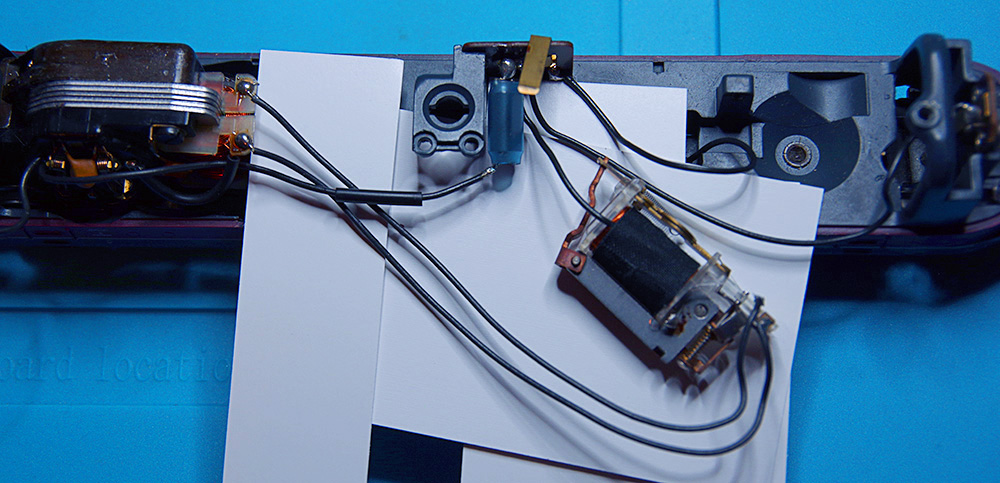
Remove the two wires on the motor from the side of the coils either by cutting or desoldering them. Be careful to avoid damaging the connection between the coil and the soldering point.
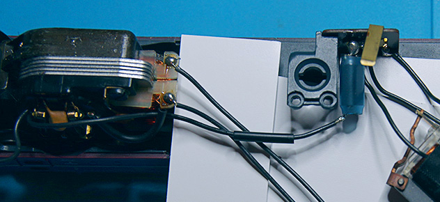
The 3rd wire runs from the motor to the direction switch, which you also remove along with the attached suppression coil. This wire will be reused later. The motor is now ready for the assembly of the components for the digital control.
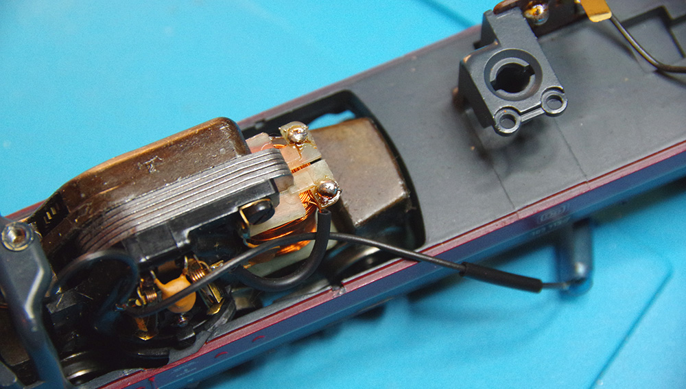
Additionally, remove the two wires to the rear and front lighting units. It is more convenient to reuse the existing wire and initially bend it out of the way a bit.
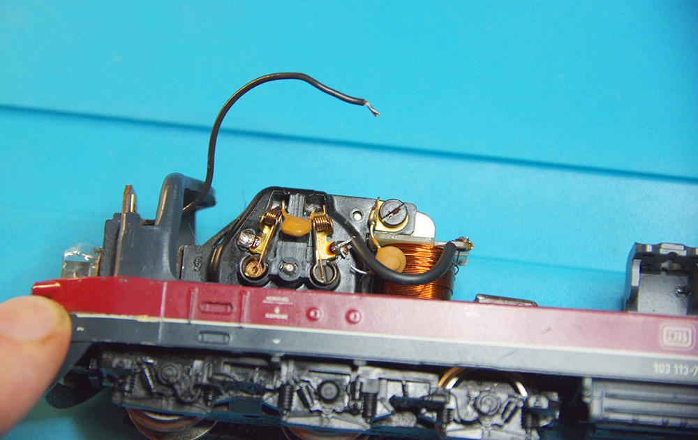
All essential components have been removed, and the chassis is ready for further assembly.
Wiring and Integration of CTC Electronics
You need for the upcoming steps:
- CTC electronics board
- 4 diodes
- 1 choke
- Wires of different lengths
First, the wires need to be cut to the appropriate length and soldered to the CTC electronics board. Ensure that the soldering time on the board is sufficient but as short as possible. If you heat the solder pads for too long, there is a risk of them detaching from the board. To estimate the respective lengths of the wires, place the board at the position of the former direction switch and measure for the following 5 wires:
| Track-B | Power supply from the track or overhead line |
| MO – | Motor wire 1 |
| MO + | Motor wire 2 |
| LI-Front | Front light |
| LI-Back | Rear light |
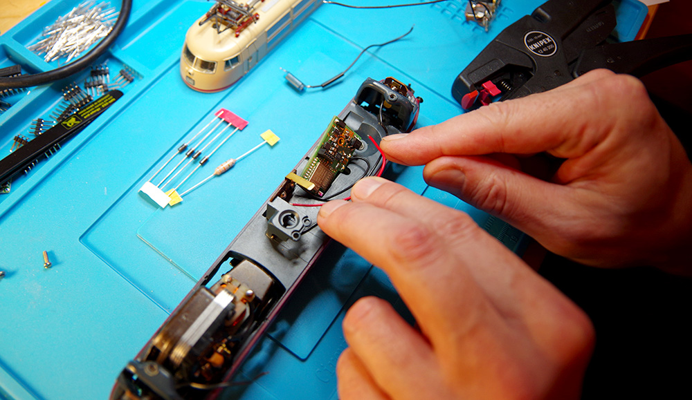
Take the cut wires and solder them to the CTC board.
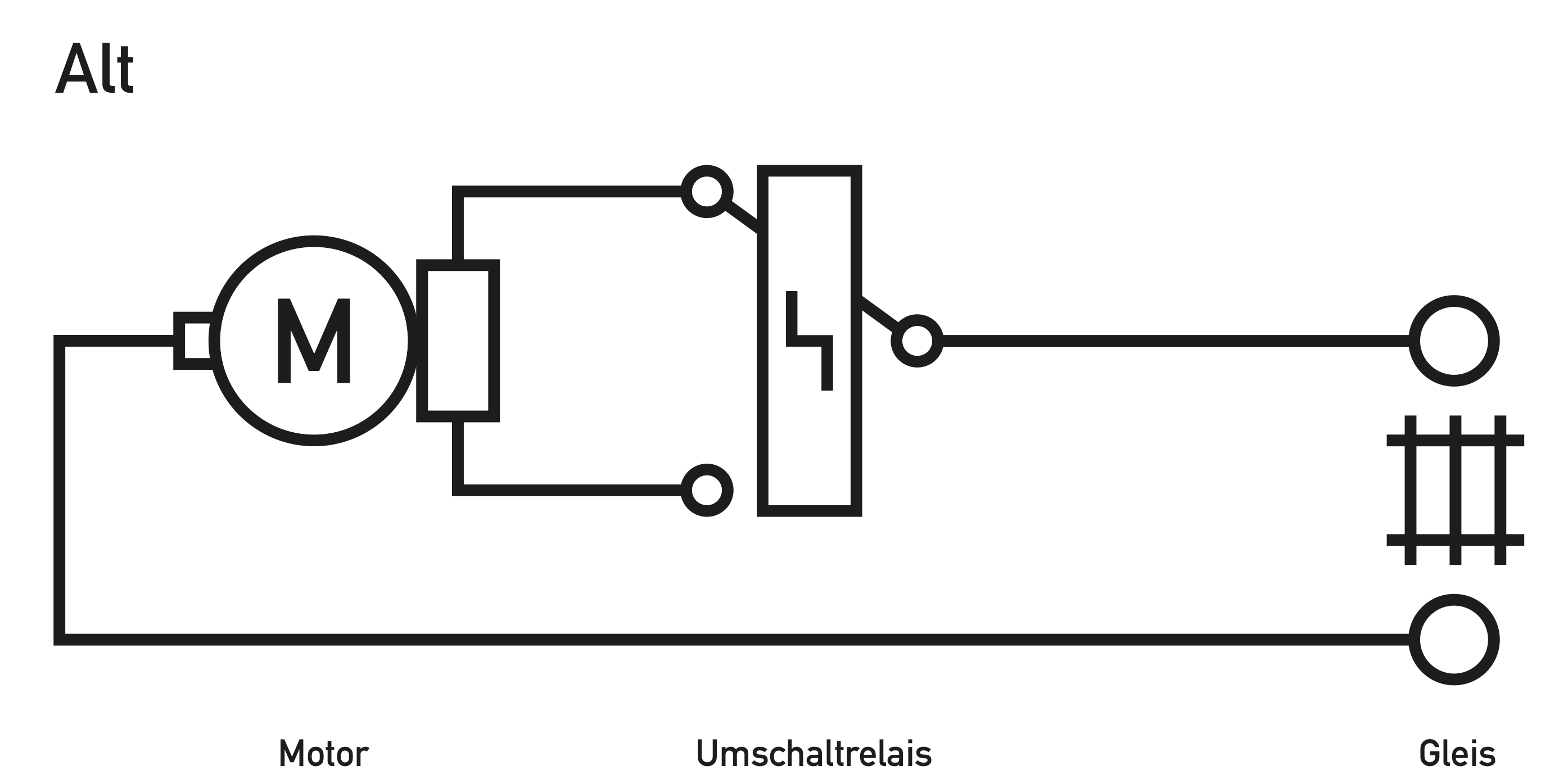
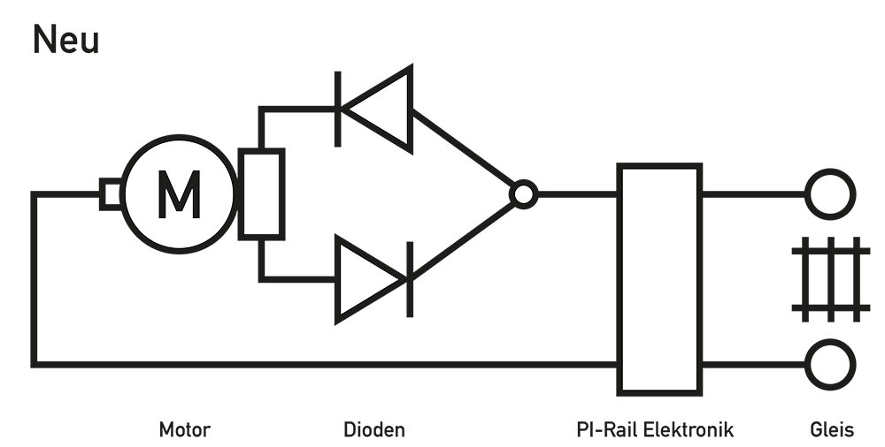
Note that in the version as done for this locomotive, the “Track-A” connection is implicitly made by the installation in the locomotive’s housing.
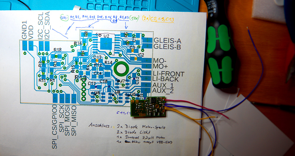
Solder one diode, as shown in the picture, into the lead for the front and rear lights. Make sure to pay attention to the “orientation” of the diodes: the “ring marking” must point towards the light.
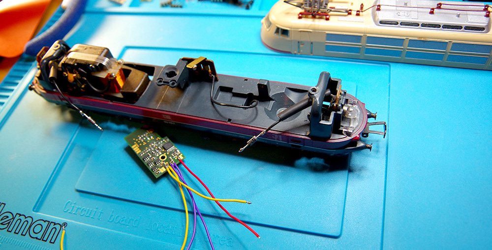
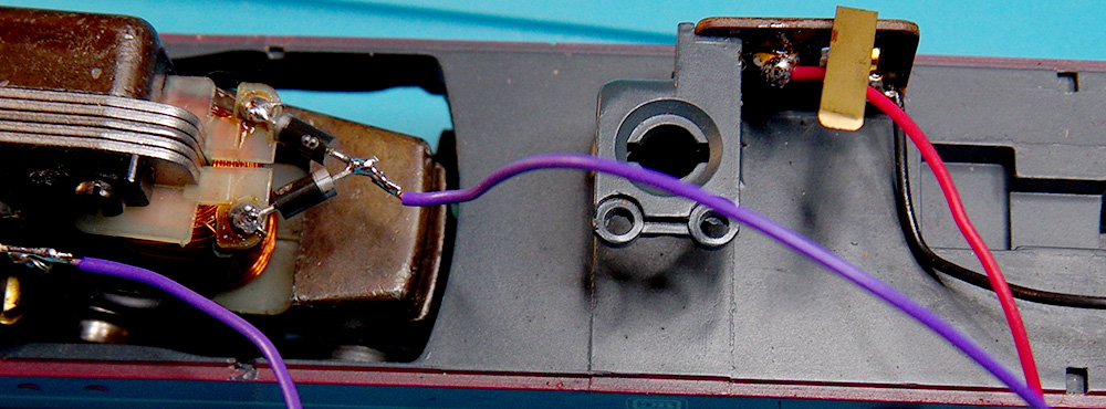
In the next step, solder the two diodes to the coil winding of the motor. As with the diodes for the lighting, you also need to pay attention to the orientation of the diodes here:
- one diode with “ring marking” towards the motor
- the other diode with “ring marking” away from the motor.
When soldering the diodes to the solder points of the motor coils, great care must be taken not to damage the sensitive wires of the coil. Under no circumstances should solder get on the coil bodies, as this could destroy them. Solder one end of each diode to the solder point of the motor coil, and the other ends of the diodes are soldered together to create the “motor diode connection”. Afterwards, you will solder the wire “MO –” from the CTC electronics to this motor diode connection.
 Soldering the diodes to the motor:
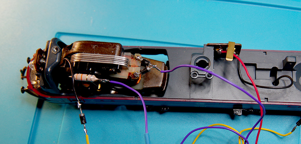
The choke for suppression is soldered where the former power lead to the motor was. Solder the wire from the “MO+” contact on the board to the choke. The choke with the wire to the electronics is now ready.
The “MO+” wire is connected to the choke:
Before soldering the wires for the front and rear lights, you can slide a suitable piece of heat shrink tubing over the wires.
Now solder the wire for the suppression capacitor to the top of the CTC board and then solder the capacitor to the wire.
Caution: This capacitor has a positive and a negative pole! Do not mix them up!
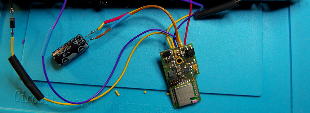
Now solder the remaining wires from the CTC board:
| Wire from Track-B | Power supply from the track or overhead line |
| Wire from MO – | Motor wire 1 to the “motor diode connection” |
| Wire from MO + | Motor wire 2 to the choke |
| Wire from LI-Front | To the front light |
| Wire from LI-Back | To the rear light |
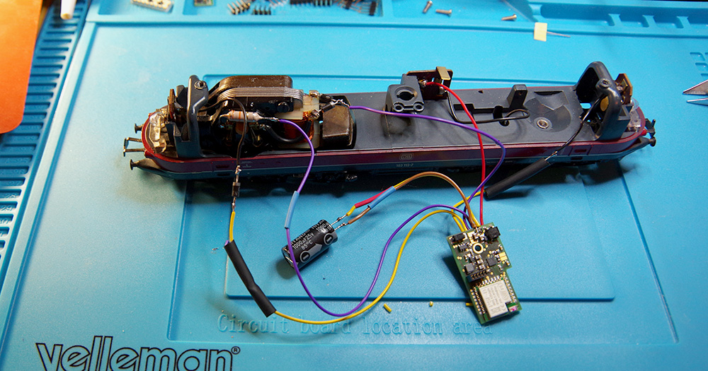
All wire connections of the CTC electronics, as well as the necessary discrete components, are installed and connected. When installing the board in the housing, make sure that the wires are not pinched, and no short circuits occur. Appropriate measures for insulation must be taken, or heat shrink tubing should be used. The CTC electronics are screwed into the place of the direction switch. With the screw, the last necessary electrical connection is made simultaneously.
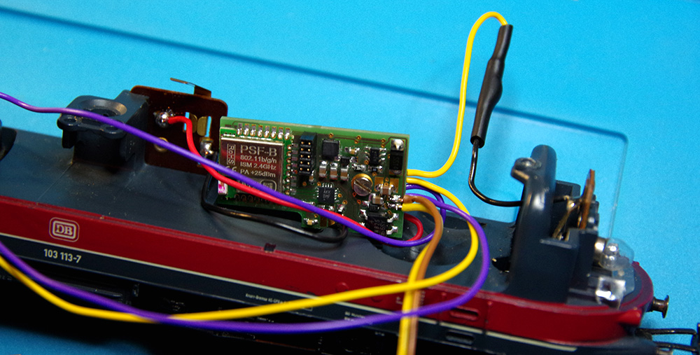
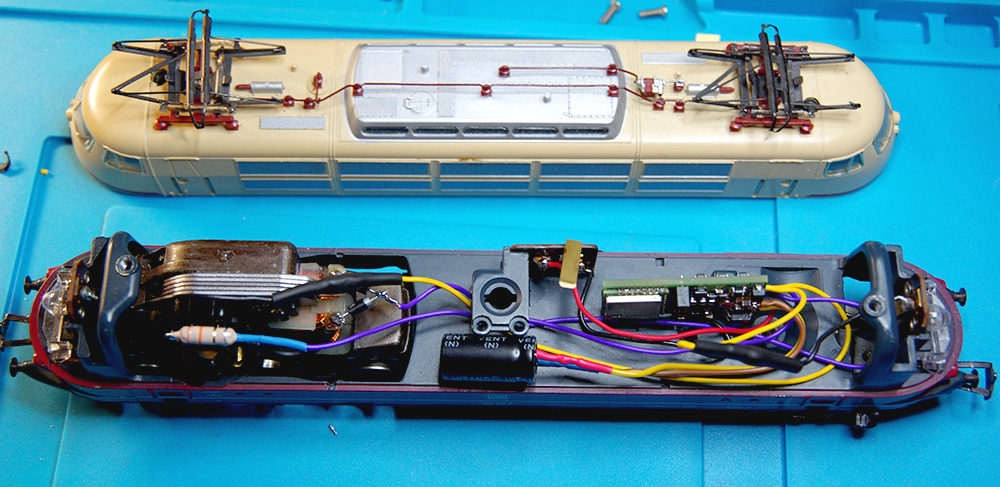
Lay the wire and the suppression capacitor on the locomotive’s lower part in such a way that no short circuits or pinching of the wires can occur when you later place the housing upper part. Now, if desired, the lower part of the locomotive can be placed on the track and a functionality test can be performed.
Installation of the Infrared Receiver
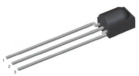
Solder a three-wire cable to the infrared receiver and secure the solder joints with heat shrink tubing. Pay attention to the following pin assignment:
| Pin 1 | Out/TX | White cable |
| Pin 2 | GND | Brown cable |
| Pin 3 | Vcc | Green cable |
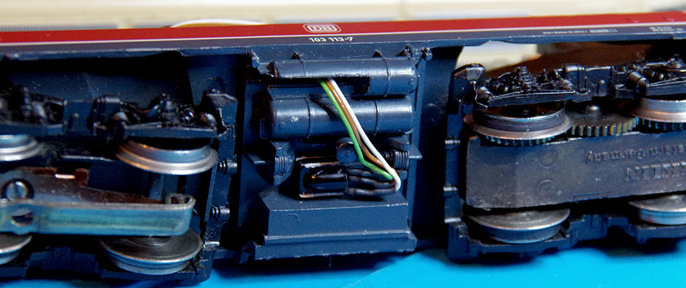
Then, thread the cable through the hole of the switch lever for the overhead line and attach the IR receiver to the bottom of the locomotive with double-sided tape or glue:
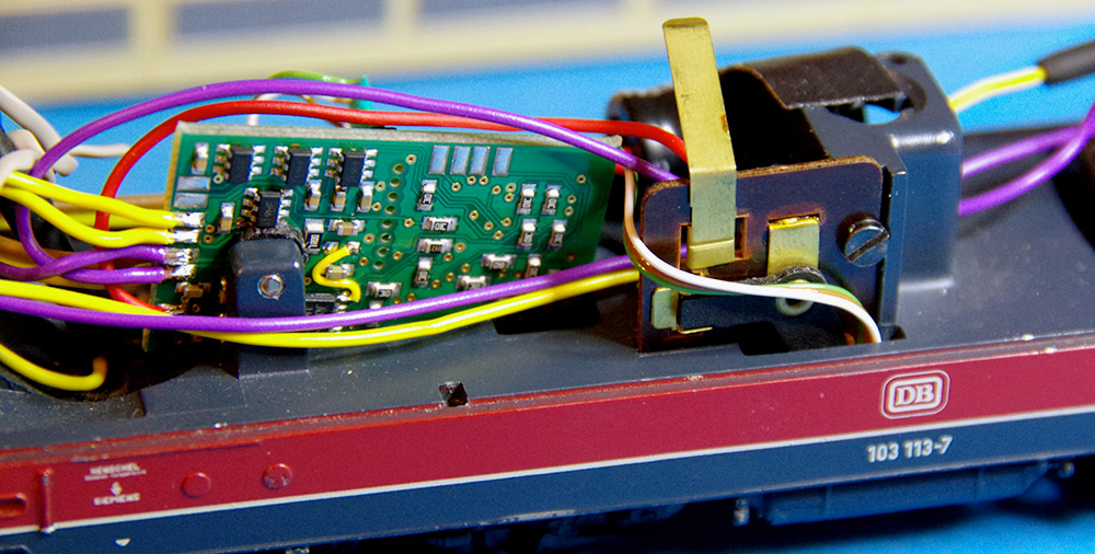
Lead the cable to the locomotive module and cut it to the appropriate length:
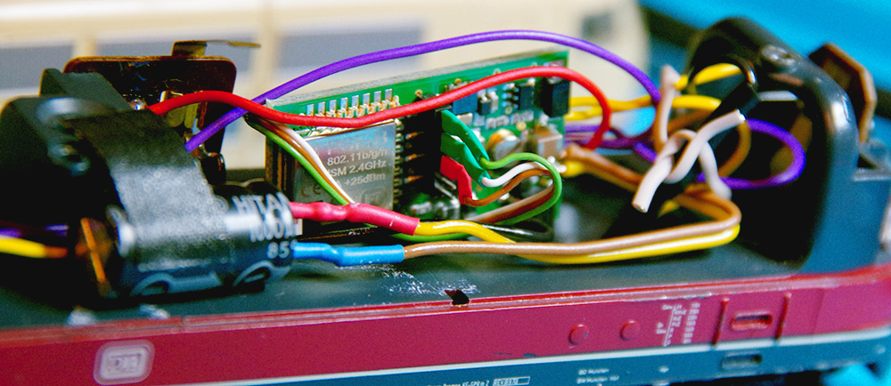
Solder the cable to an 8-pin header with a 1.27 mm pitch according to the following table:
| Pin 1 | - | ||
| Pin 2 | - | ||
| Pin 3 | GND | Brown cable | Red heat shrink tubing |
| Pin 4 | - | ||
| Pin 5 | Out/TX | White cable | Green heat shrink tubing |
| Pin 6 | - | ||
| Pin 7 | Vcc | Green cable | Green heat shrink tubing |
| Pin 8 | - |
Then insert the header into the module so that the red-marked pin points towards the module side with a corner:
Reassembling the Housing
Carefully place the upper part of the locomotive housing onto the lower part, paying attention to wires that might shift. Screw the housing together.
- Categories:
- CTC-Module (10) ,
- Umsteigen (8)


