| Feature | Description |
|---|---|
| Optimized for | Installation under the layout |
| Dimensions | 74 x 46 mm |
| Processor | Espressif ESP-32 |
| Input voltage | approx. 9V to 24V DC (smoothed direct current), digital current, AC with buffer capacitor |
| Power outputs | 8x 1.2 A, short-circuit proof (total max. 1.5 A) |
| Servos | 2x (require external power supply) |
| Total current max. | 2 A |
| Sensor inputs | 4x Digital (optocoupler with 2 kOhm), e.g., for switch track |
| Interfaces | 2 CTC-IR-balises (each max. 12 mA), NFC reader |
| Current online passive | approx. 20 mA at 16V |
| Current booting | approx. 50 mA at 16V plus switching current for initialization of the outputs |
In the overview “Switching with CTC” you will find additional modules and links to installation instructions. ```null## Pin Assignment
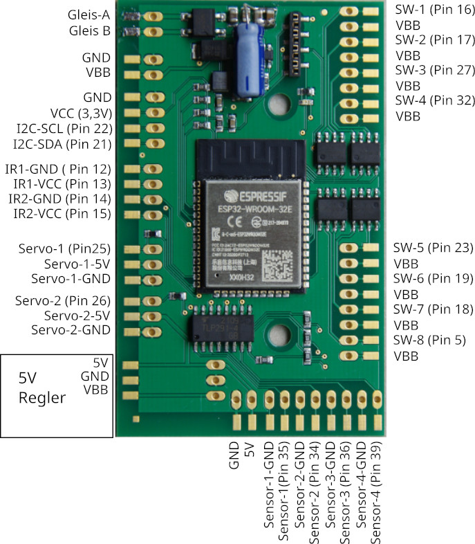 null## Connectors
We supply the CTC-Multi-I/O-Board by default with screw terminals:
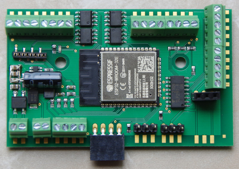
Alternatively, you can order it without connection terminals and then equip it with connectors in a 2.54 mm grid according to your needs. Here are a few examples (in the image from left to right):
- Spring terminal RIA CONNECT
- Screw terminal PHOENIX-CONTACT - our standard configuration
- Vertical socket strip: Keep in mind that a plug connection via a socket strip hanging vertically down can easily come loose.
- Angled socket strip
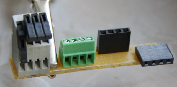
Due to the risk of short circuits from the exposed pins, we generally advise against using pin headers.null## Connection
Notes:
- When choosing the input voltage, please remember that the motors, lamps, etc., connected to the CTC module must also tolerate this voltage!
Standard Configuration
- Connect the contacts Rail-A and Rail-B with the track or power supply. It does not matter whether it is a digital central unit or a power supply unit, as long as the maximum voltage of 24 V is not exceeded. Since a rectifier is connected at the input, it doesn’t matter which pole you connect with Rail-A and Rail-B.
- Connect actuators (turnouts, signals, …) with the switching outputs (SW-x). Here, the negative pole is connected to the respective switching output (SW-x) and the positive pole to VBB. The outputs labeled VBB are all internally connected, i.e., it doesn’t matter which one you use, and you can also connect several actuators together to one of the VBB contacts.
- Connect the CTC IR balises with IR1-GND (negative pole, green) and IR1-VCC (positive pole, red) or IR2-GND and IR2-VCC. See also the data sheet of the CTC-IR-Balise. Please do not forget the resistor (typically 1 kOhm, min. 330 Ohm) in the IR balise; otherwise, the Multi-I/O board is damaged.
- Connect sensors (e.g., switching rails) with the 4 sensor inputs. Here, only pay attention to the polarity (GND = negative pole) and a maximum voltage of 24 V. A 2 kOhm resistor and an optocoupler on the Multi-I/O board ensure that the electronics cannot be damaged.
- Connect the Wagon Reader (NFC Reader): The NFC Reader is powered via VCC (3.3V) and GND.
For data transmission, NFC-TX and NFC-RX are used.
Note: When using the NFC Reader, the second IR receiver cannot be utilized.
Pin assignment to switches in the app can be configured (Cfg.xml).
For the two (optional) servos:
- Connect the power supply for the servos either via the 5V/GND terminals or solder on a piggyback board.
- Connect the servo connections with the servo outputs (Note: Pin assignment of the connectors is not standardized!).
NOTE: For AC supply, the (in the first image blue) support capacitor is absolutely necessary.null## Outdoor Variant
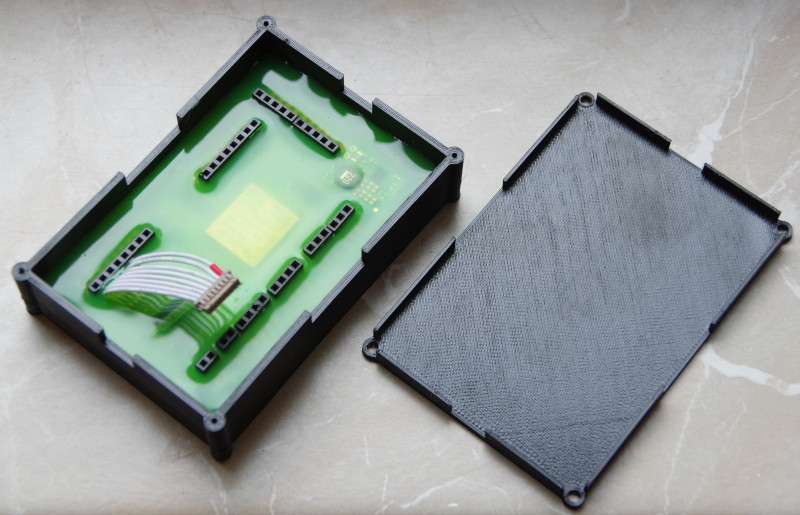
For operation in the garden (outdoor), after unsuccessful experiments with spray paint, we decided to have the electronics completely enclosed in resin. This is somewhat more expensive, but it still works even when the railway is underwater.
