In this article, I will show you how to equip the LGB turnout drive (No. 12010) including the turnout lantern (No. 12040) with a CTC-TurnoutModule-G.
Important: This documentation was created before our decision regarding cable colors. The cable colors in the photos do not correspond to this decision!
Here, at the beginning, the fully converted turnout drive:
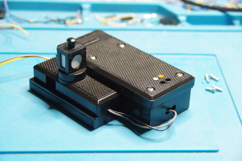
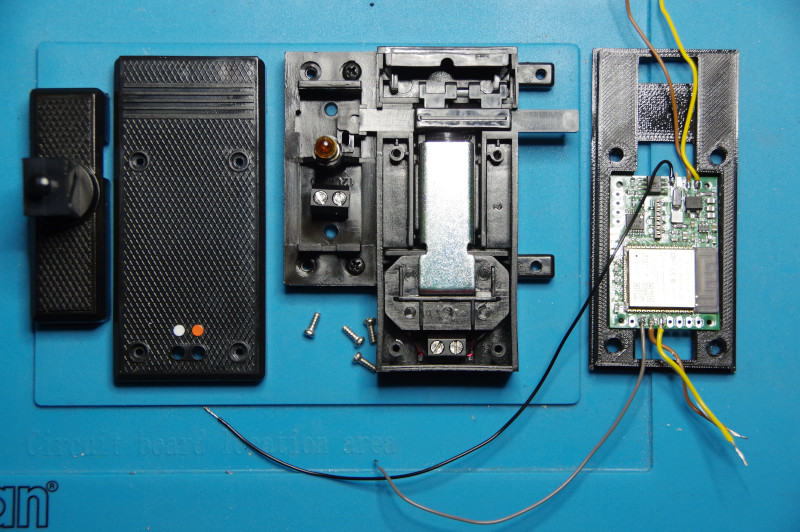
First, the turnout lantern is attached according to the instructions included with the product. Next, the covers from the turnout and lantern are removed. In the following image, I have already prepared the mounting frame and the CTC-TurnoutModule-G on the right:
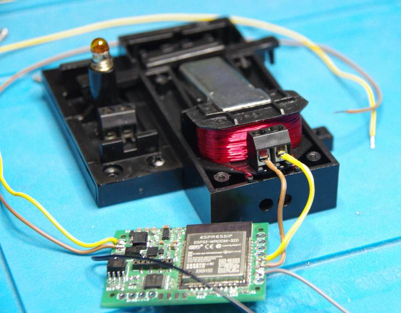
Next, the turnout drive is lifted just enough to access the terminal clamps. Then the short cables soldered to HB-1 and HB-2 are connected to the terminal clamps of the turnout drive:
Furthermore, the cables to connect the turnout lantern (HB-3 and GND, gray and black) are threaded through the holes of the turnout drive:
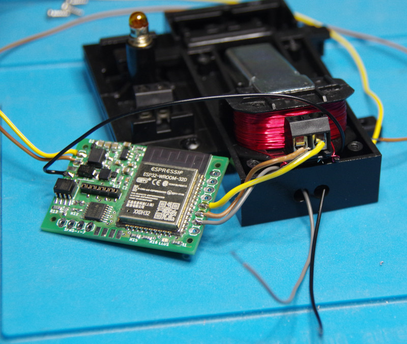
When reinserting the drive, make sure that no cables are pinched!
Insert the CTC module into the mounting frame and guide the track connections (Track-A and Track-B, brown and yellow) out of the other side of the housing. For this purpose, a 3 mm hole was drilled into the removable cover.
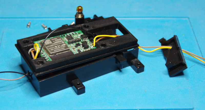
Now we screw the cables (gray and black) to the terminal clamps of the turnout lantern. Since it is still a light bulb, we don’t have to worry about polarity:
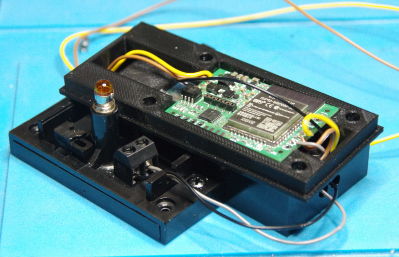
Then we place the cover on the turnout lantern. Ensure that the guide pin lands in the intended hole. In the picture on the right, the cover and the longer screws provided by CTC are already prepared:
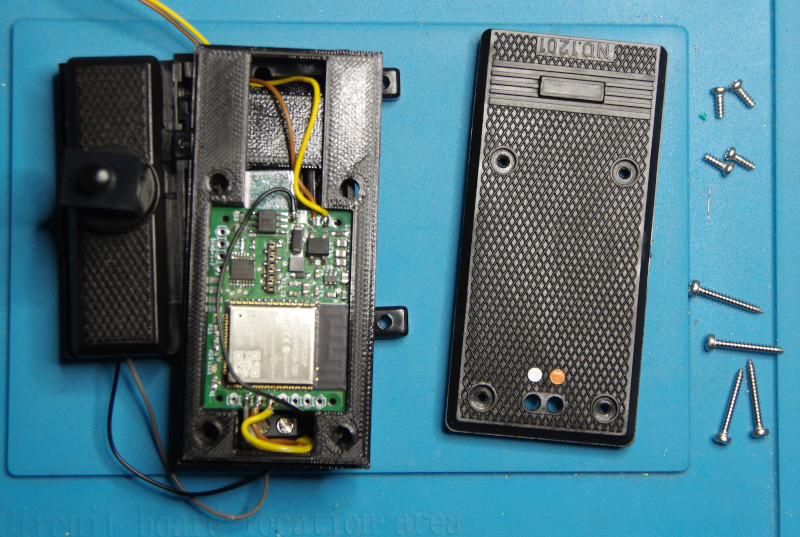
Finally, we position the mounting frame, place the cover on it, and secure it with the longer screws.
- Categories:
- CTC-Module (10) ,
- Umsteigen (7)


