This installation guide is suitable for the turnouts 24611, 24612, 24671, 24672:
as well as the two slender turnouts 24711, 24712 from the C-track program and the Startup turnouts 20611, 20612, 20671, 20672 from Märklin.
All of them use one of the drives 74490, 74491, or 74492, which have a receptacle for the JST ZH connector system. On the CTC-Turnout-Module with the item number WI-M-4L-C1, there is a cable with a matching connector.
Installing and Connecting the CTC Module
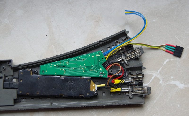
The CTC module is placed on the pins intended for the Märklin decoder and pressed on.
This is how the drive is connected to the CTC turnout module:
- Insert the plug of the cable soldered to the CTC turnout module into the turnout drive.
- Plug the cable lug on the brown cable onto a tab labelled “0” (rail).
- Plug the cable lug on the red cable onto a tab labelled “B” (center conductor).
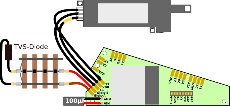
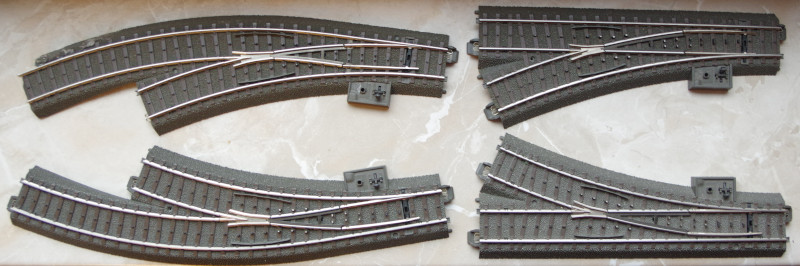
The following picture shows a right turnout with a built-in turnout drive and CTC turnout module.
A signal or an additional turnout can be connected to the three individual cables (2x blue and 1x yellow). Two IR balises can be connected to the four-pin socket.
Connecting the CTC Module to Wi-Fi
If the CTC turnout module is not yet connected to the model railway Wi-Fi, this should be your first step. Instructions can be found in the operating manual under Chapter 3.1 “Connecting Modules to Wi-Fi”.
Open Configuration
You can find a registered CTC turnout module under its name in the module list in the CTC app. There, you click on the pencil icon to open the “Control Box Configuration”.
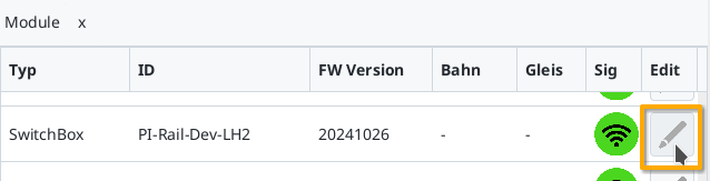
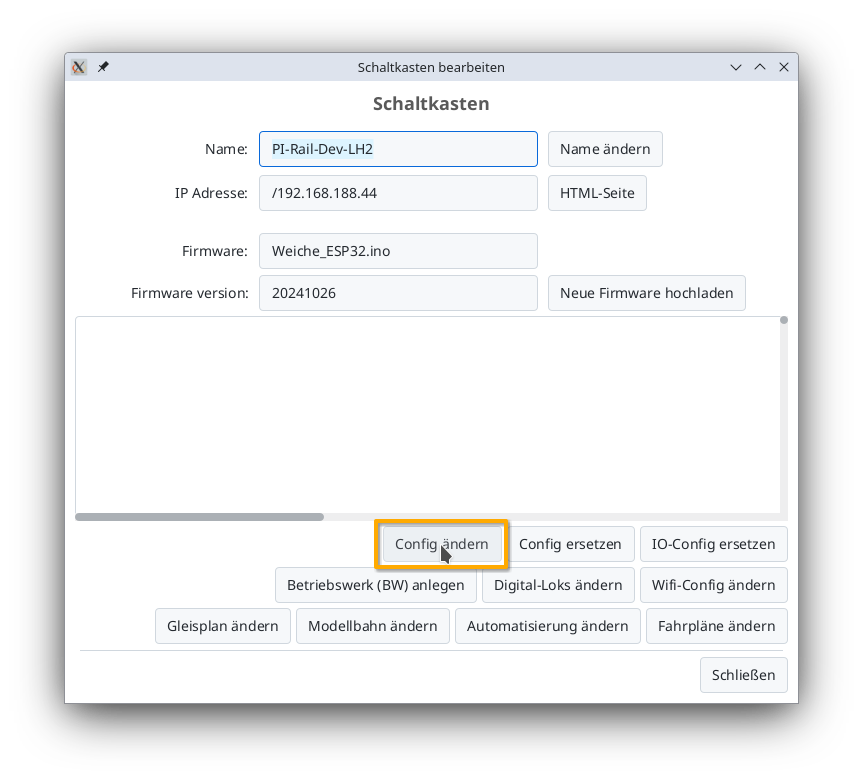
There, you click on the “Change Config” button:
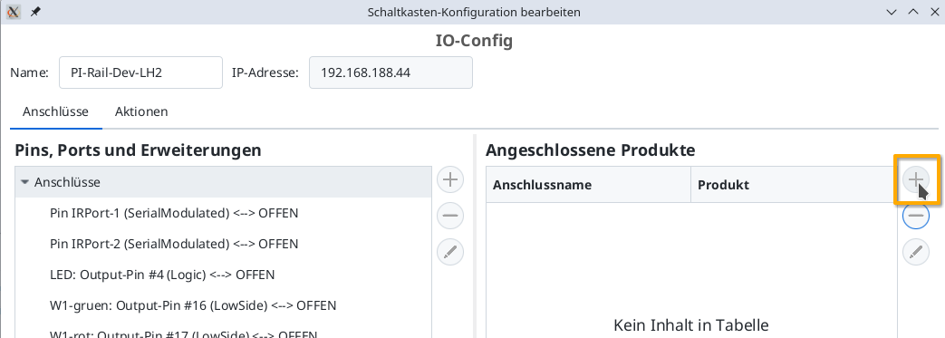
Add Product
In the Config dialog, click on the plus button to the right of “Connected Products” to select what kind of product you’ve connected:
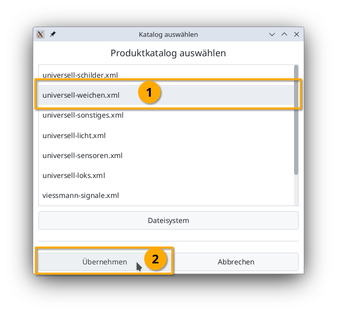
Select the product catalog “universal-turnouts” and then click on “Apply”:
Give your turnout a meaningful name and select the appropriate product and product configuration. Then click on “Apply”:
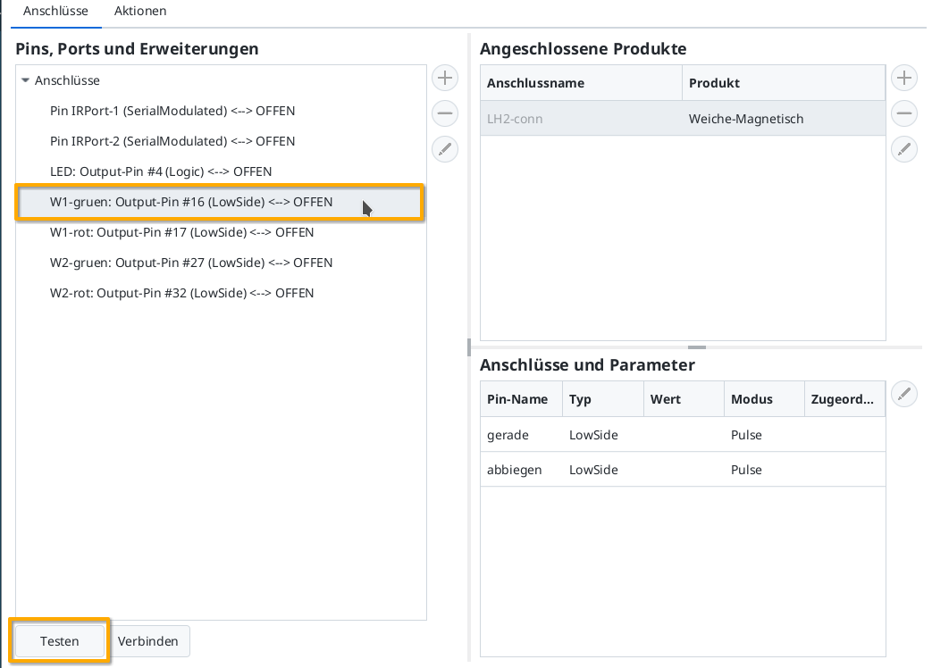
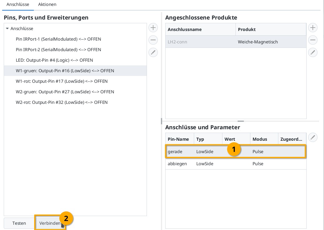
Then, by clicking the “Test” button, you can check whether the turnout is switching and in which direction. In my example, W1-green switches to straight. Therefore, I now select the line “straight” under “Connections and Parameters”. By clicking “Connect”, you assign the “W1-green: Output-Pin #16” highlighted on the left to the “straight” connection:
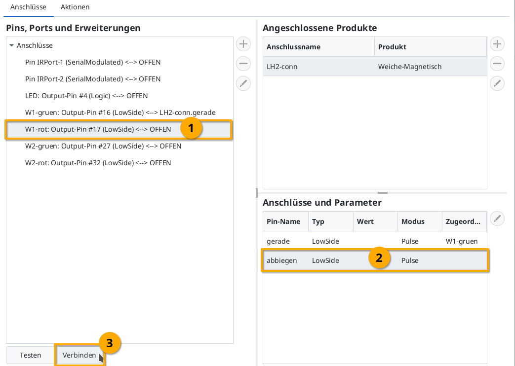
Then, in the same way, you also connect “W1-red” (Output-Pin #17) to the “turn” connection:
Upload Configuration
Once all pins are connected, you can click the “Upload” button to save the changes to the CTC turnout module:
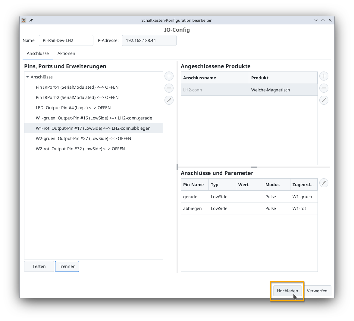
The CTC turnout module restarts.
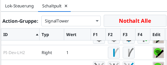
Turnout on the Switchboard
After a few seconds, the newly configured turnout appears on the switchboard: