


Compared to the classic digital decoders, you can get fairly close to seeing the actual status of a turnout in the CTC app without any special measures. This is achieved by having the CTC app display the state based on the feedback from the turnout, and not just knowing that it has dispatched the order.
What the CTC app still doesn’t know is if the turnout is mechanically blocked or if it is thrown manually. At least for LGB turnouts, there is a perfect solution, which I would like to introduce in this article.
Under the item number 12070, LGB offers an additional switch that is attached to the turnout drive. It contains two micro-switches that are operated by the turnout toggle. As the additional switch is connected to the turnout point blade without any additional spring, it can reliably reproduce its position.
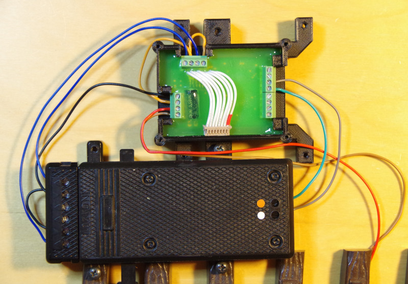
In addition to the usual connection of an LGB turnout to the CTC-Turnout Module G (red, brown, green, grey) we still connect:
- GND (black) with the two middle connections of the LGB additional switch.
- VBB (orange) with the connections SENS-1 and SENS-2 of the CTC-Turnout Module G.
- The two outer connections of the LGB additional switch (blue) with the connections SENS-1-GND and SENS-2-GND of the CTC-Turnout Module-G.
Note: The photo still shows the older CTC-Turnout Module-G:
Register the CTC Module on the Wi-Fi
If the CTC turnout module has not yet been registered on the model railway Wi-Fi, you need to do this first. You can find instructions on how to do this in the user manual in Chapter 3.1 “Register Modules on the Wi-Fi”.
Open Configuration
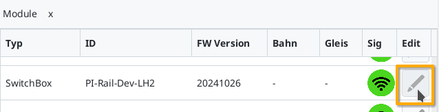
You can find a connected CTC turnout module under its name in the module list in the CTC app. Click on the pencil icon there to open the “Switchbox Configuration”.
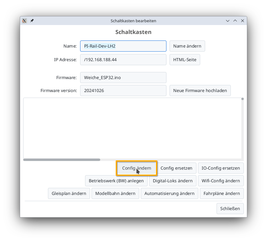
There, click on the “Change Config” button:
Add Product
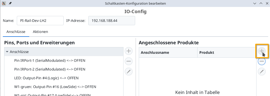
In the Config dialog, click on the plus button to the right of “Connected Products” to select what type of product you have connected:
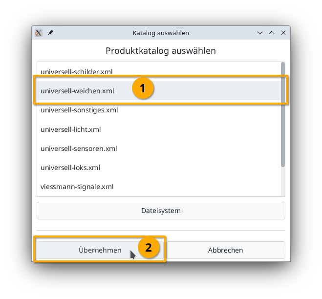
Select the “universal-turnouts” product catalog and then click on “Apply”:
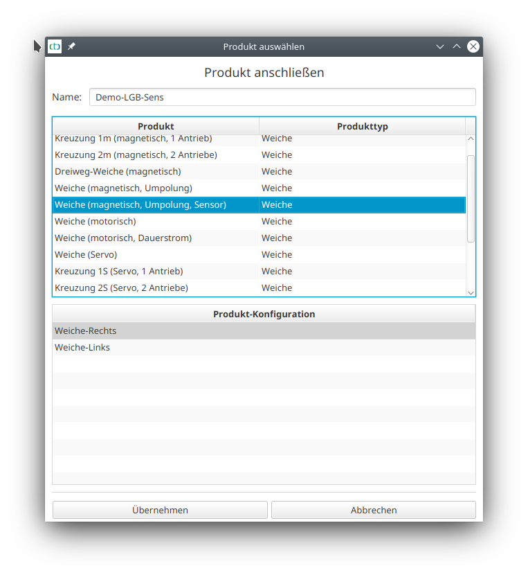
Give your turnout a meaningful name and select the appropriate product and product configuration. Then click on “Apply”:
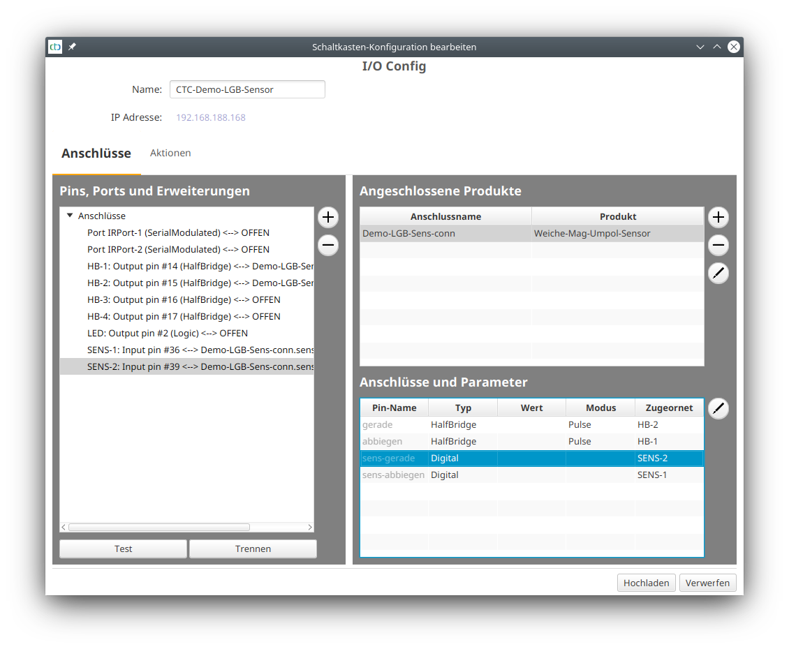
Then you still assign the connections of the product and get the following configuration:
Upload Configuration
Once all pins are connected, you can click the “Upload” button to save the changes to the CTC turnout module:
The CTC turnout module will restart.
Turnout in the Control Panel
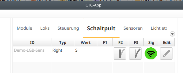
The newly configured turnout appears in the control panel after a few seconds:
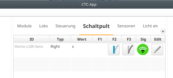
The blue marking for the position of the turnouts now, however, shows the actual position, as determined by the two sensors contained in the CTC-turnout module-G. This can simply be tested by adjusting the turnout with your finger instead of via the CTC app.
If, for example, the turnout can only partially switch due to a small stone, meaning it gets stuck halfway, you would know this because neither of the two positions is marked in blue:
If desired, you can now also link triggers with the two turnout positions and thus receive a logic that responds to the actual turnout position instead of the switching command.