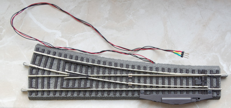
This installation guide applies to the turnout 55421:
as well as the turnouts 55170, 55171, 55220, 55221, 55222 55223, 55226, 55227, 55228, 55420, 55422, 55423, 55426, 55427, 55428 from Piko’s A-Track program.
They all use the 55271 drive. In the example, a 3-pin connector is soldered to the cables: On the CTC-Turnout Module with the item number WI-M-4L-U, three cables were found, to which a suitable socket was soldered in the example.
Installing and Connecting the CTC Module
The CTC module is mounted on or under the model railway layout.
Here is how you connect the actuator to the CTC turnout module:
- Plug the pin header of the turnout actuator into the socket on the CTC turnout module.
- Connect the brown cable with the negative pole of the power supply or the track.
- Connect the red cable with the positive pole or the other track.
TODO Connection diagram
The following picture shows a right turnout with a built-in turnout actuator and CTC turnout module. TODO turnout with actuator and CTC module
The remaining three individual cables (2x blue and 1x yellow) can be connected to a signal or another turnout. Two IR balises can be connected to the four-pin socket.
Registering the CTC Module to the Wi-Fi
If the CTC turnout module has not yet been registered on the model railway’s Wi-Fi, you must do this first. You can find the instructions for this in the user manual in Chapter 3.1 “Registering Modules on the Wi-Fi”.
Open Configuration
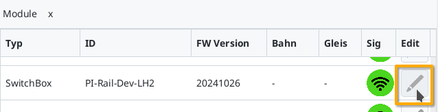
You can find a registered CTC turnout module under its name in the module list in the CTC app. There, click on the pen icon to open the “Control Panel Configuration”.
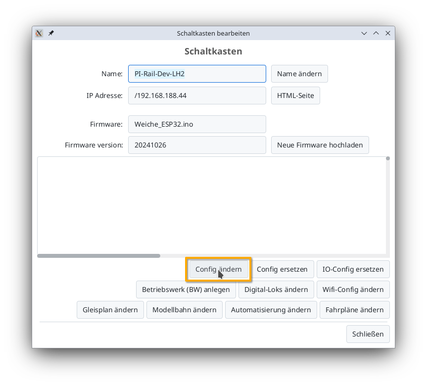
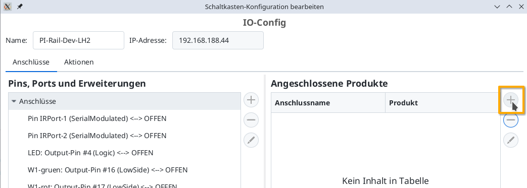
Then, click on the “Change Config” button:
Add product
In the Config dialog, click the plus button to the right of “Connected Products” to select which type of product you have connected:
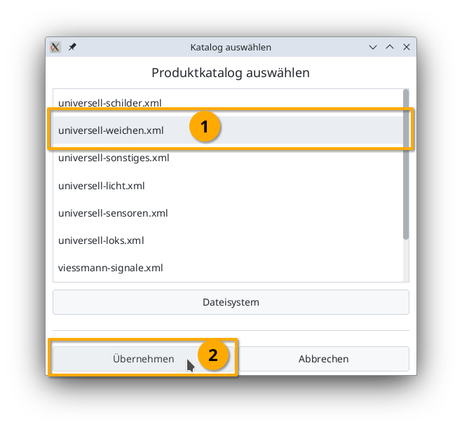
Select the product catalog “universal-turnouts” and then click on “Apply”:
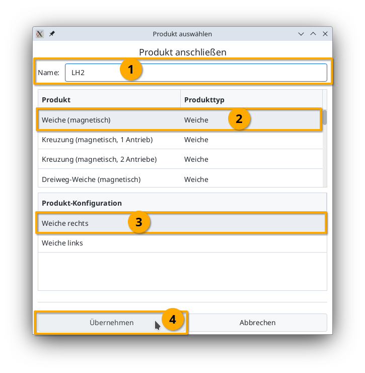
Give your turnout a sensible name and select the appropriate product and product configuration. Then click on “Apply”:
Connect product
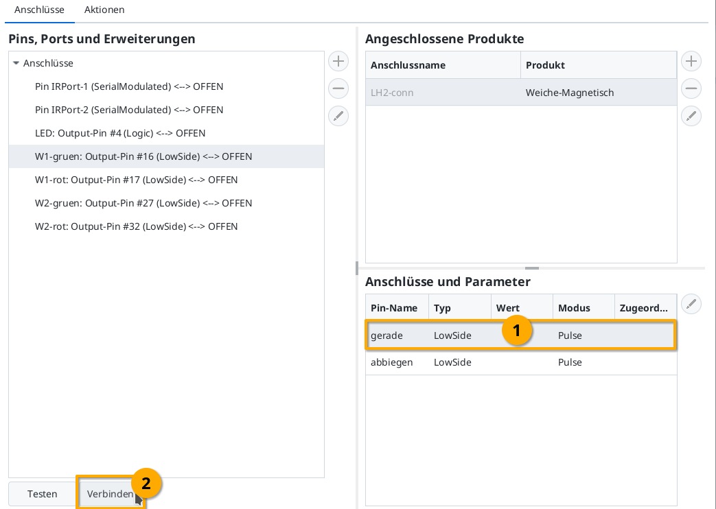
Now you need to specify which connections of the CTC module the turnout is connected to. The connector used above is soldered to “W1-green” and “W1-red”. You select “W1-green”:
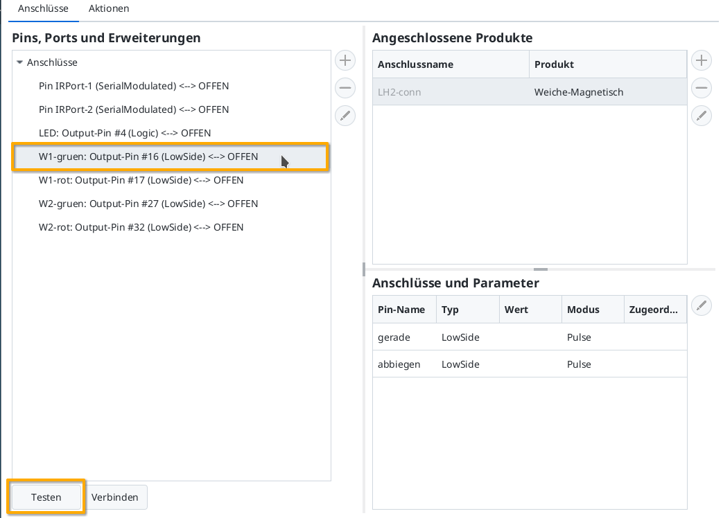
Then by clicking on the “Test” button, you can check whether the turnout switches and in which direction. In my example, W1-green switches to straight. Therefore, I now select the line “straight” in “Connections and Parameters”. By clicking on “Connect”, you assign the “straight” connection to the “W1-green: Output-Pin #16” marked on the left:
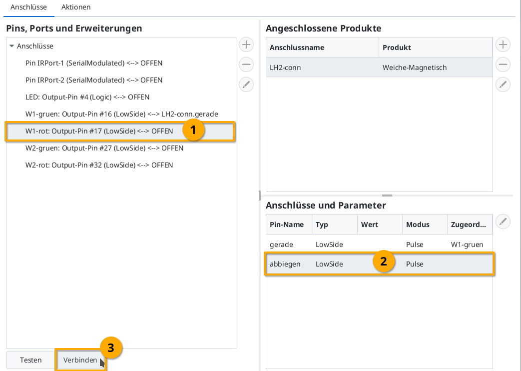
Then, in the same way, you connect “W1-red” (Output-Pin #17) to the “turn” connection:
Upload Configuration
Once all pins are connected, you can click the “Upload” button to save the changes to the CTC turnout module configuration:
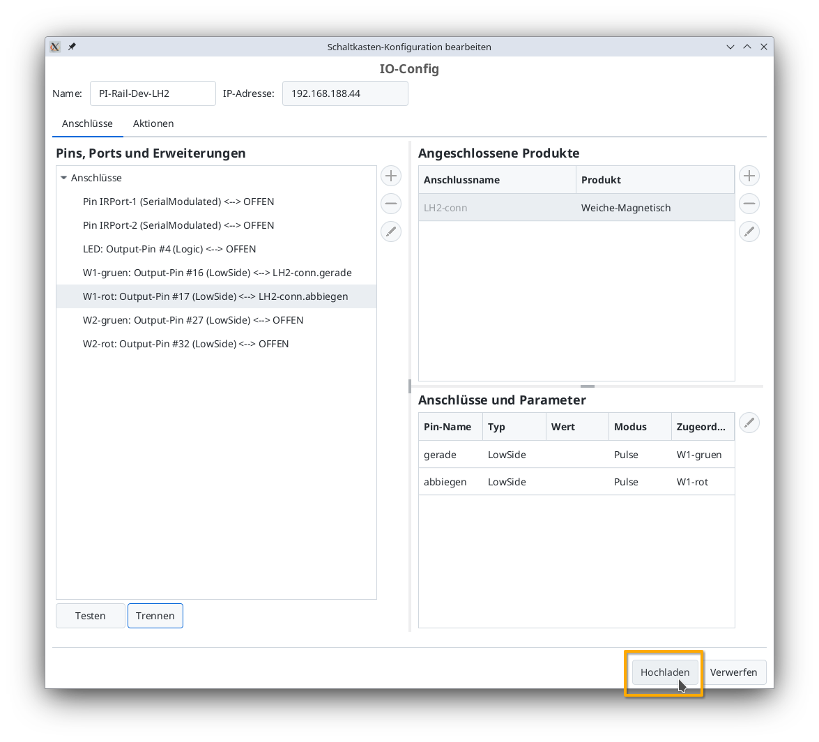
The CTC turnout module will then restart.
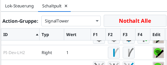
Turnout on the Control Panel
After a few seconds, the newly configured turnout appears on the control panel: