In this article, I’ll show you how to install a CTC turnout module with the article number WI-M-4L-U into a Märklin M-track.
First, we solder suitable connectors to the CTC turnout module:
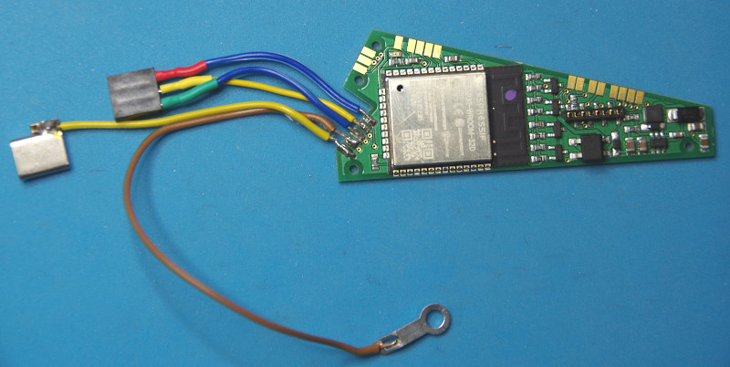
Note: The variant in this photo is actually an old version of the CTC turnout module, which was not yet suitable for AC (alternating current), as it lacks the support capacitor (see also the note at the end of the article).
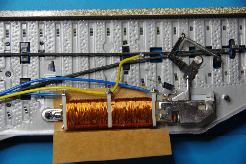
As with converting old locomotives, care must be taken to ensure that all connections to the tracks are secured with a diode. Otherwise, you risk irreparable damage to the CTC module.
In the case of our M-track turnout, the lamp is connected to the electromagnet drive on one side and directly to the track on the other side.
To protect the electronics, we insert a diode into this connection:
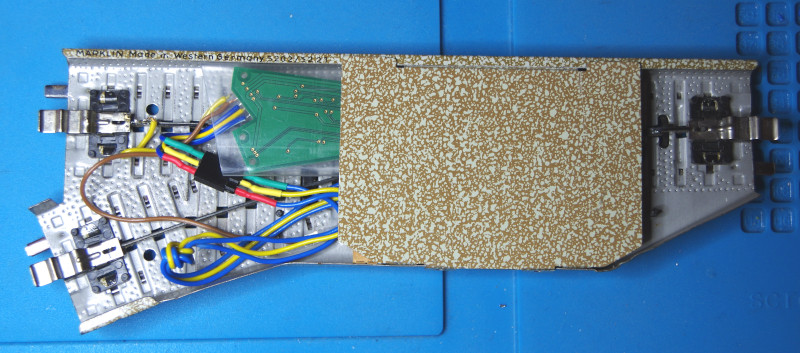
We get one track contact (ground) via a soldering lug under the mounting of the turnout drive (brown cable).
We get the other track contact either via the known tabs or, as we do, by soldering it to the center conductor (yellow cable).
The turnout drive itself is connected as usual via the yellow and the two blue cables:
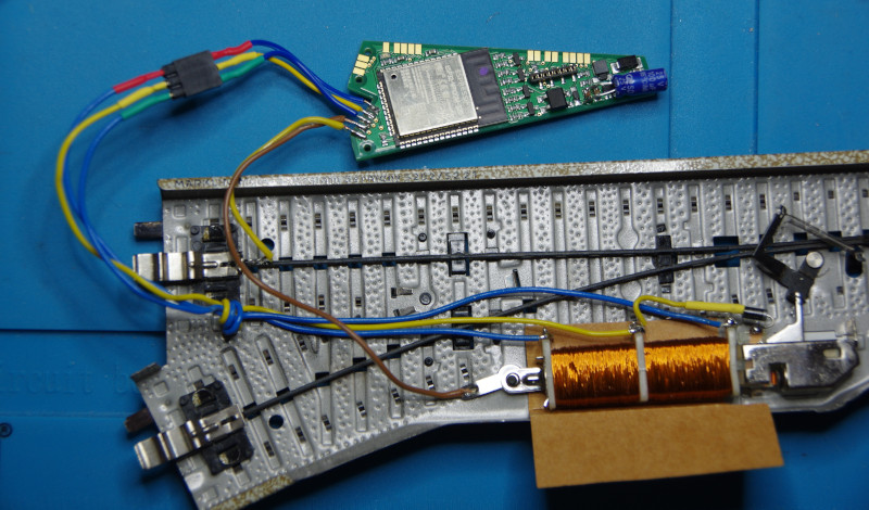
WARNING: For operation with alternating current (AC), such as that provided by the classic Märklin transformers, the CTC module must definitely be complemented by a support capacitor, as seen in the picture above (blue component).
Now the CTC module is slid into a shrink tubing and can then be pinched by the lid of the turnout drive, as the introductory image shows.
Registering the CTC Module with Wi-Fi
If the CTC turnout module is not yet registered with the model railway Wi-Fi, this is the first thing you need to do. You can find the instructions in the user manual in Chapter 3.1 “Registering modules with Wi-Fi”.
Open Configuration
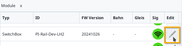
You can find a connected CTC turnout module under its name in the module list in the CTC app. There, click on the pencil icon to open the “switch panel configuration”.
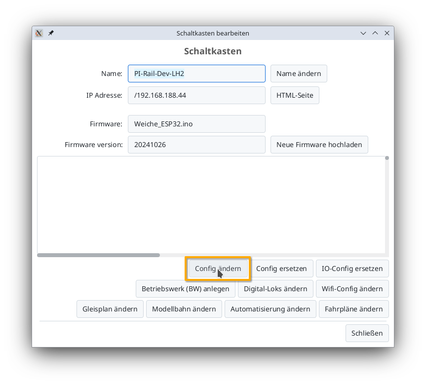
There, click on the “Change config” button:
Adding a Product
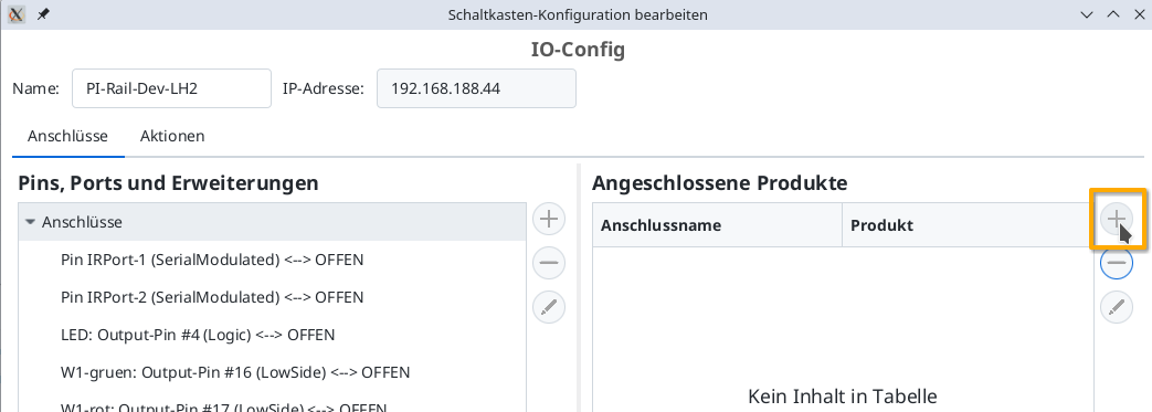
In the Config dialog, click on the plus button to the right of “Connected Products” to select what kind of product you have connected:
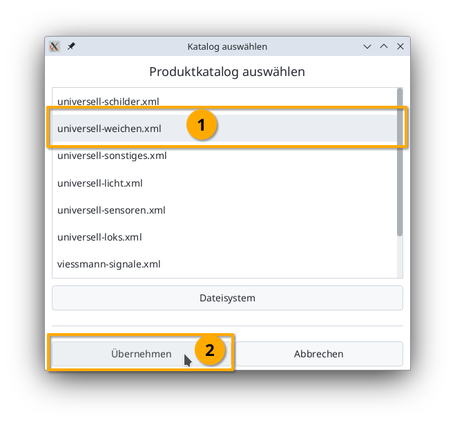
Select the product catalog “universal-turnouts” and then click on “Apply”:
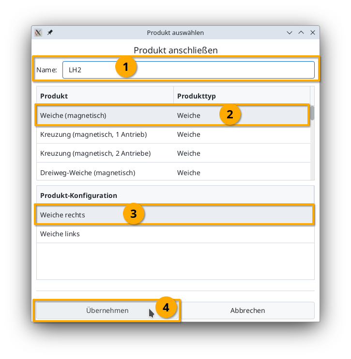
Give your turnout a meaningful name and select the appropriate product and product configuration. Then click on “Apply”:
Connect the Product
Now you need to specify which connections of the CTC module are connected to the turnout. The plug used above is soldered to “W1-green” and “W1-red”. You select “W1-green”:
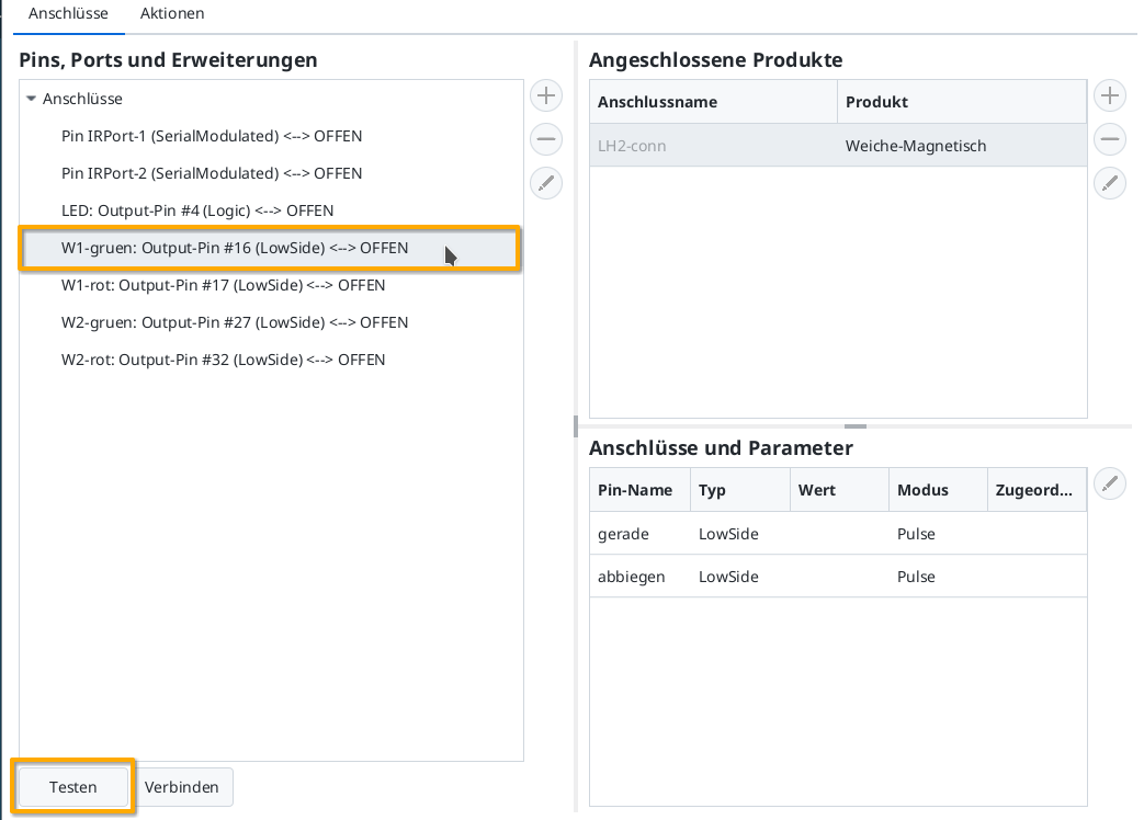
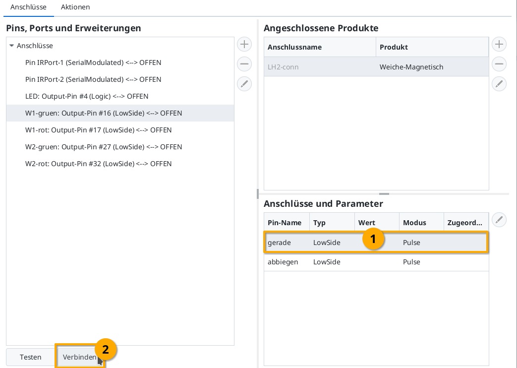
Then by clicking on the “Test” button, you can check whether the turnout switches and in which direction. In my example, W1-green switches to straight. Therefore, I now select the “straight” line in “Connections and Parameters”. By clicking on “Connect”, you assign the “straight” connection to the “W1-green: Output-Pin #16”, which is marked on the left:
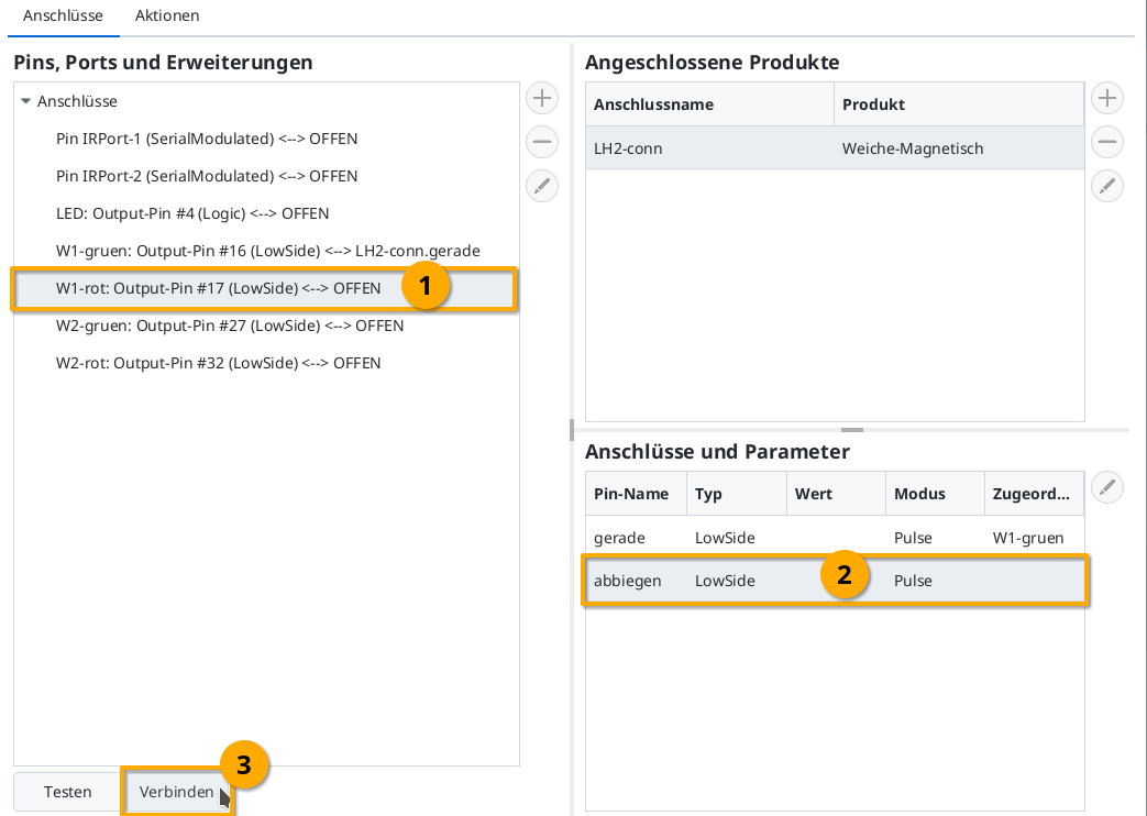
Then in the same way, connect “W1-red” (Output-Pin #17) with the “deviate” connection:
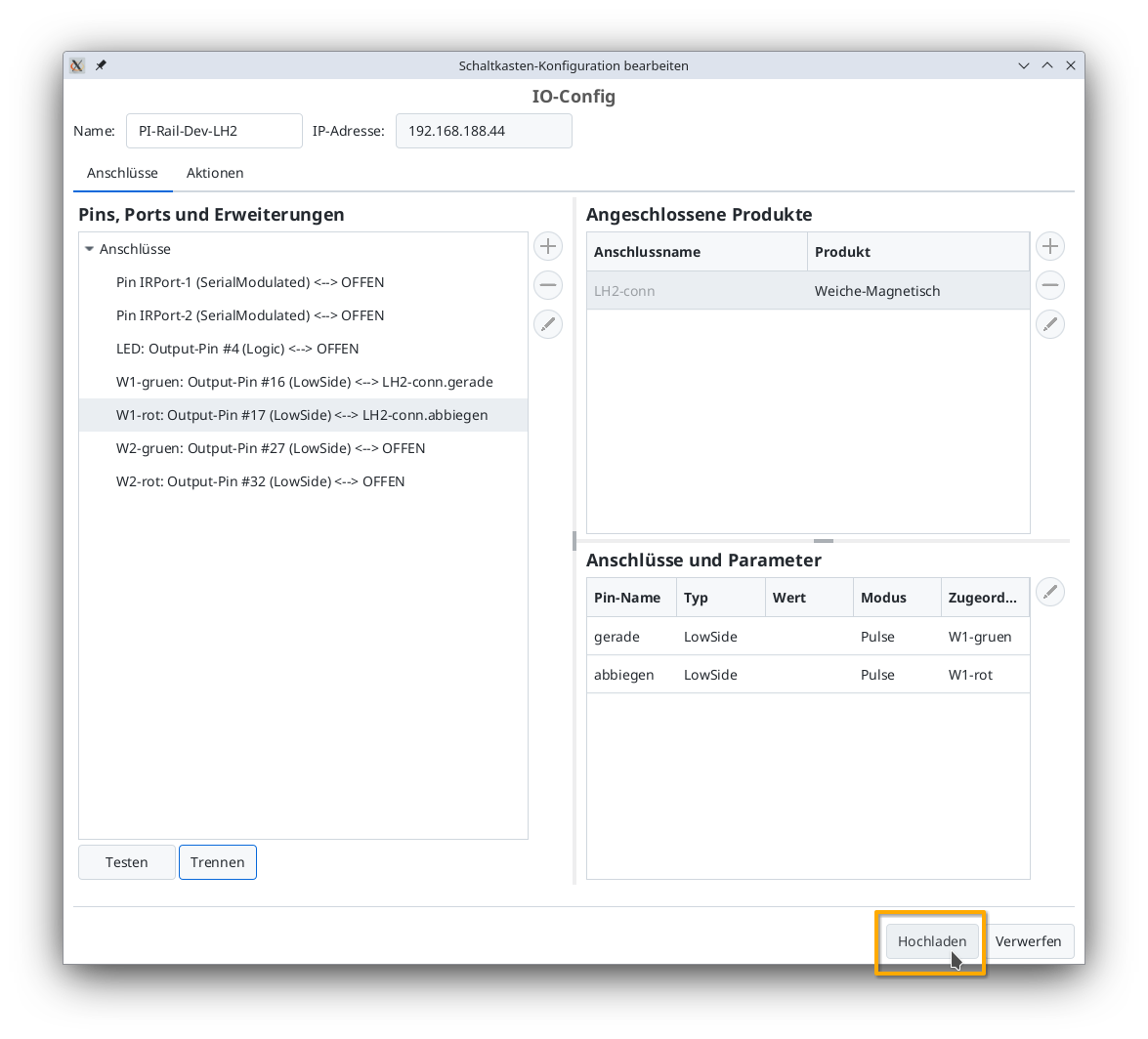
Upload Configuration
Once all pins are connected, you can click the “Upload” button to save the changes to the CTC turnouts module:
The CTC turnouts module will restart.
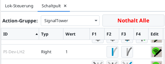
Turnout on the Control Panel
After a few seconds, the newly configured turnout appears on the control panel: