The CTC-Locomotive-Module-G2 is optimized for installation in Gauge 1 and garden railway locomotives. Locomotives with many features benefit from the two motor connections, 10 switching outputs, and 2 servo connections of this locomotive module. In addition, a SUSI3 sound module can be connected.
| Property | Description |
|---|---|
| Optimized for | Garden railway locomotives, locomotives with high power consumption, locomotives with 2 motors |
| Dimensions | 81 x 30 mm (old Locomotive Module G: 78 x 30 mm) |
| Processor | Espressif ESP32 |
| Input voltage | approx. 9 V to 24 V DC, digital power or AC (with supporting capacitor) |
| Motor output | 2x DC motor: Peak 6 A or 3.5 A |
| Power outputs (SW) | 6x 1.2 A LowSide |
| Half-bridges (HB) | 4x 2.5 A (old Locomotive Module G: 4x 1.0 A) |
| Servos | 2x (require external power supply or additional circuit board) |
| Total current max. | 15 A |
| Interfaces | CTC-NFC-Reader, 2x sensor input (optocouplers), CTC-IR-receiver |
| Sound | SUSI3-Classic (old Locomotive Module G with adapter on servo pins) |
| Current online passive | 35 mA at 22 V |
| Startup current | 50 mA at 22 V plus switching current for initializing the outputs |
We offer the CTC-Locomotive-Module-G2 in two variants, equipped with different driver modules
-
for two motors with 3.5 A peak each
Buy G2-3.5A now -
for two motors with 6 A peak each
Buy G2-6A now
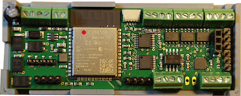
In current LGB locomotives, the motor blocks (including track contact) are connected via a ribbon cable with a 2.54 mm grid socket. For this, we offer a variant of the CTC-Locomotive-Module-G2 where two screw terminals have been replaced with suitable pin headers.
- The older CTC-Locomotive-Module-G1 (without SUSI) is only available in the variant with 6 A peak
Buy G1-6A now
In the overview “CTC-Locomotive Modules” you will find more modules and links to installation instructions.
Pin Assignment Locomotive Module-G2
The pin assignment of all four variants of the CTC locomotive module-G2 is identical. The different driver chips can only be identified by the print on the chips. We mark the 3.5 A variant with a red dot and the 6 A variant with a green dot. Here is the universal variant with screw terminals:
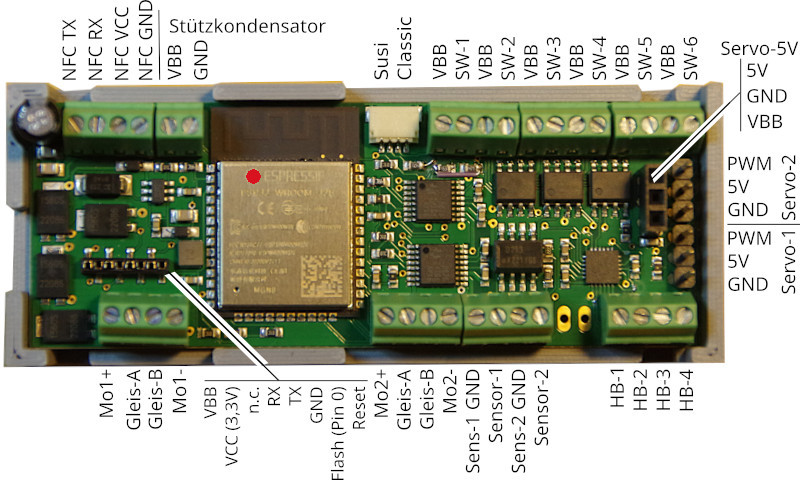
Here is the variant designed for newer LGB locomotives with pin headers for motor and track connection:
Pin Assignment (Older) Locomotive Module-G
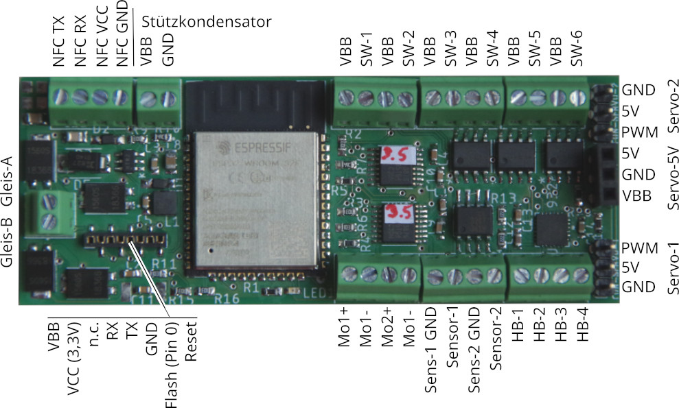
Notes on the old Locomotive Module-G:
- The pin labelling for “Servo-5V” was wrong until 19.06.2023 (VBB and 5V switched)!
- On the CTC locomotive modules-G delivered before 09.07.2021, the SW connections were swapped in pairs. This can be corrected by software configuration.
Connection
Notes:
- When choosing the input voltage, always remember that motors, lamps, etc. connected to the CTC module must also be able to withstand this voltage!
Standard configuration
- Connect the Track-A and Track-B contacts with the track or power supply. It doesn’t matter whether you supply the track with an analog transformer, a digital control center or a power supply as long as the maximum voltage of 24V is not exceeded. Since there is a rectifier at the input, it also doesn’t matter which pole you connect to Track-A and Track-B. But both Track-A and Track-B connections must each be connected to the same track contact.
- Connect the backup capacitor (electrolytic, min. 400 uF, recommended 6800 uF) to VBB (positive pole) and GND.
- Connect the motors each with Mo1+ and Mo1- (or Mo2+ and Mo2-).
- Connect the negative poles of lights each with one of the SW-x connections. Connect the positive pole each with any VBB connection.
- Optionally connect further SW connections e.g. with negative pole of the electric coupling, the smoke generator or further lighting. Again, the positive pole must be connected each with any VBB connection.
- Connect the CTC-NFC-Reader to NFC-RX, NFC-TX, as well as VCC and GND.
- Plug the SUSI3 sound module into the SUSI3-Classic socket.
The assignment of the pins to switches in the app can be freely configured (Cfg.xml).
Additional Connections
For servos, e.g. to be able to raise and lower pantographs, you need a separate 5V power supply. You can purchase suitable boards from us.
Connecting the servos:
- Plug the power supply board onto the socket strip. Pay attention to the correct polarity.
- Plug the servos onto the pin headers. Here too, the polarity must be adhered to.
The assignment of servos to switches in the app can be freely configured (Cfg.xml).
Mounting Bracket
The CTC locomotive module-G and -G2 always come with a mounting bracket. The photo shows the CTC locomotive module-G:
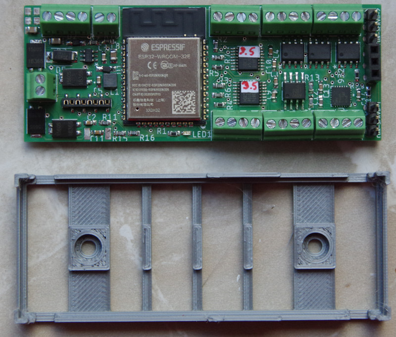
The distance between the screw holes is 49 mm, as with the lead weight of the LGB-Köf (D10).
