The CTC-Locomotive-Module-H0a is sold out and will no longer be offered. As a replacement, we recommend the CTC-Lokmodul-M3 with cables or with PluX22 and our CTC-Adapter for PluX22.
The CTC-Locomotive-Module-H0a is optimized for installation in old analog locomotives where one pole of the lighting is permanently connected to the housing. The four switching outputs are sufficient for front and rear lights and, for example, two electrical couplings or one electrical coupling and a smoke unit.
| Feature | Description |
|---|---|
| Optimized for | Analog conversion |
| Dimensions | 35 x 20 mm |
| Processor | Espressif ESP8285 |
| Input voltage | approx. 9 V to 24 V DC, digital current or AC (with support capacitor) |
| Motor output | DC motor: continuous current 1.0 A, peak 2.8 A |
| Power outputs | 4x 0.5 A high-side |
| Max. total current | 2 A |
| Interfaces | CTC-IR receiver, I2C |
| Passive online current | approx. 20 mA at 16 V |
| Boot current | approx. 50 mA at 16 V plus switching current for output initialization |
In the overview “CTC Locomotive Modules” you will find further modules and links to installation instructions.
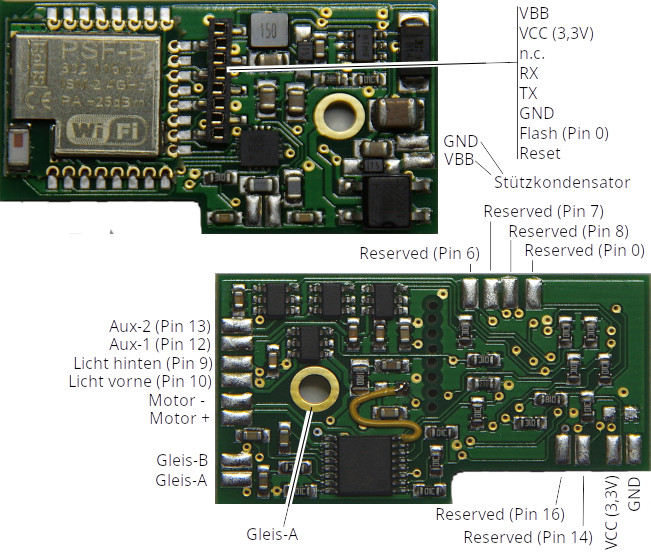
Connection
Notes:
- When selecting the input voltage, always ensure that motors, lamps, etc., connected to the CTC module can also handle this voltage!
Standard Configuration
- Connect the Gleis-A and Gleis-B contacts to the track or power supply. Alternatively, Gleis-A can also be connected via a screw (using the hole in the PCB). It does not matter whether you power the track with an analog transformer, a digital command station, or a power supply unit, as long as the maximum voltage of 24 V is not exceeded. Since a rectifier is connected to the input, polarity does not matter when connecting Gleis-A and Gleis-B.
- Connect the support capacitor (electrolytic, min. 400 µF, recommended 1000 µF) to VBB (positive terminal) and GND.
- Connect the motor to Motor + and Motor – (for connecting the electromagnet of universal motors, see separate instructions).
- Connect the positive terminal of the front and rear lights to the corresponding terminals. Connect the negative terminal to GND or via a diode to the negative terminal of the track connection.
- Optionally, connect the Aux terminals to the positive terminal (e.g., for electric couplings). Connect the negative terminal to GND or via a diode to the negative terminal of the track connection.
- Connect the CTC IR receiver to the programming port (RX, VCC, GND).
The assignment of pins to switches in the app can be freely configured (Cfg.xml).
Additional Connections
The I2C bus and the other “Reserved” pins are not supported by the current firmware.
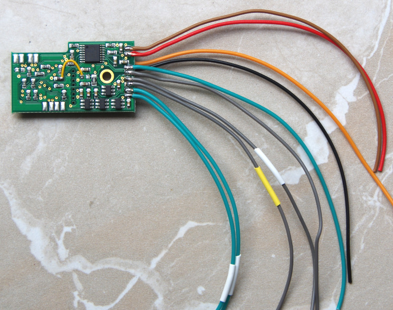
Delivery
We always supply the CTC locomotive module H0a with cables according to our color scheme: