The CTC-Lokmodul-H0d is no longer available. As a replacement, we recommend the CTC-Lokmodul-M3 with cables or with PluX22 and our CTC-Adapter for PluX22.
The CTC-Lokmodul-H0d is optimized for installation in older locomotives that are either already digital or were also offered as digital variants. Locomotives with many functions benefit from the 10 switching outputs and 2 servo connections of this locomotive module. With an additional motor driver module, a second motor can also be controlled.
| Feature | Description |
|---|---|
| Optimized for | Older digital locomotives, locomotives with many functions, locomotives with 2 motors |
| Dimensions | 35 x 20 mm |
| Processor | Espressif ESP32 |
| Input voltage | approx. 9 V to 24 V DC, digital current or AC (with support capacitor) |
| Motor output | 1x DC motor: continuous current 1.0 A, peak 2.8 A 1x connection for additional motor driver module |
| Power outputs | 8x 0.5 A LowSide 2x 1.0 A High-/LowSide |
| Servos | 2x (require external power supply) |
| Max. total current | 2 A |
| Interfaces | CTC-IR receiver, I2C |
Note: In the overview “CTC-Lokmodule” you will find further modules and links to installation instructions.
Pin Assignment
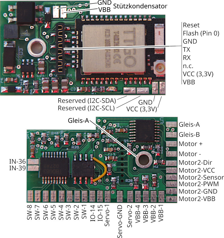
Connection
Standard Configuration
- Connect contacts Track-A and Track-B to the track or power supply. Alternatively, Track-A can also be connected via a screw (hole in the PCB). It does not matter whether you power the track with an analog transformer, a digital command station, or a power supply unit, as long as the maximum voltage of 24 V is not exceeded. Since a rectifier is connected at the input, it also does not matter which pole you connect to Track-A and Track-B.
- Connect the support capacitor (electrolytic, min. 400 µF, recommended 1000 µF) to VBB (positive pole) and GND.
- Connect the motor to Motor + and Motor - (for connecting the electromagnet of universal motors, see separate instructions).
- Connect the negative terminals of the front lights to SW-1 and the rear lights to SW-2. Connect the positive terminal of each to any VBB connection.
- Optionally, connect additional SW terminals (e.g., to the negative terminal of the electrical coupling, smoke unit, or additional lighting). Connect the positive terminal of each to any VBB connection.
- Connect the CTC IR receiver to the programming connector (RX, VCC, GND).
The assignment of pins to switches in the app can be freely configured (Cfg.xml).
Additional Connections
The I2C bus, servos, the second motor, and the reserved pins are not supported by the current firmware. Please contact us if needed.