| Feature | Description |
|---|---|
| Processor | Espressif ESP-32 |
| Dimensions | 53 x 31 mm (including screw terminals) |
| Input Voltage | approx. 9V to 24V DC (smoothed direct current), digital current, AC with support capacitor |
| Power Outputs | 4x 2 A half-bridge (Version G1: 1 A) |
| Servos | 2x (only Version G2, requires external power supply) |
| Max. Total Current | 3 A (Version G1: 2 A) |
| Sensor Inputs | 4x digital via optocoupler with 2 kOhm (2x before 2023) |
| Interfaces | 2 CTC IR-balise (max. 12mA each), I2C Bus |
| Passive online power | TODO |
| Booting power | TODO plus switching current for output initialization |
The CTC-Turnout Module-G is available in four versions:
- With screw terminals and a holder for mounting underneath or on the model railway board.
- With screw terminals and a case optimized for LGB turnouts and PIKO-G turnouts.
- As an outdoor variant with electronics encapsulated in the case.
- Without screw terminals (solder connections) for mounting in an H0 track bed (on request).
In the overview “Switching with CTC” you will find more modules and links to installation instructions.
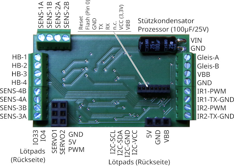
Version G2 with screw terminals (from 2023)
Old Version (G1) with screw terminals (until 2022)
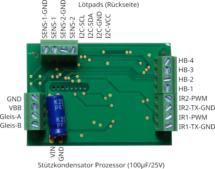
Connection
Notes:
- When choosing the input voltage, please keep in mind that the motors, lamps, … connected to the CTC module must also tolerate this voltage!
Standard configuration:
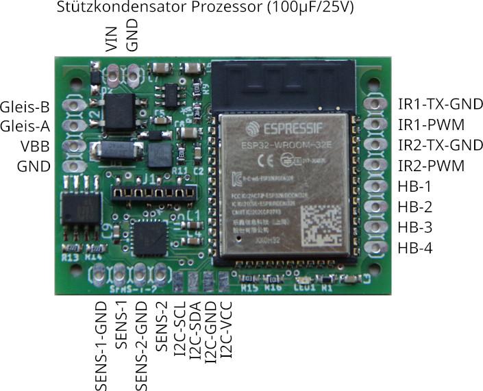
- Connect the contacts Track-A and Track-B to the track or the power supply. It doesn’t matter whether it’s a digital control unit or a power supply, as long as the maximum voltage of 24 V is not exceeded. As there is a rectifier at the input, it also doesn’t matter which pole you connect to Track-A and Track-B.
- Connect the switching connections of the turnout drive to HB-1 and HB-2 (or HB-3 and HB-4).
- Connect the CTC-IR-balises to IR1-GND (minus pole, green) and IR1-VCC (plus pole, red) or IR2-GND and IR2-VCC. Also refer to the datasheet of the CTC-IR-Sender. Please do not forget the resistor (typically 1 kOhm, min. 330 Ohm) in the IR-balise, otherwise the CTC-Turnout Module-G will be damaged.
- Connect sensors (e.g., switching tracks) to the 4 sensor inputs. Starting from version 2023 (G2), polarity doesn’t need to be considered anymore. The current is limited by a 2 kOhm resistor, so no further current limiting is necessary up to 24 V.
The pin assignment for switching can be configured in the app (Cfg.xml), as well as the duration of the switching pulse.
Additional Connections
- The I2C bus (I2C-SCL and I2C-SDA) and the pins IO4 and IO33 are not supported by the current firmware. In the outdoor variant, these pins are also not accessible due to encapsulation.
NOTE: For AC power supply, the (blue in pictures) support capacitor is mandatory.
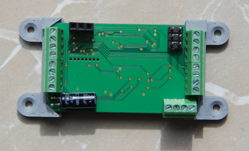
With Holder
Here you can see the Turnout-G2 with holder:
Universal Case
Here you can see the Turnout-G2 in our universal case:
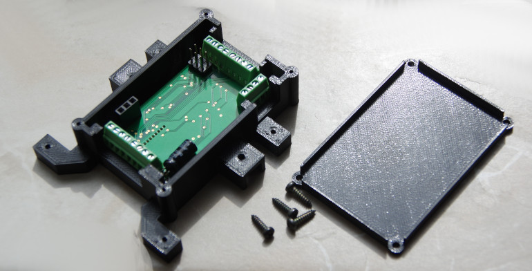
It can be mounted either completely separately (not pictured) or side mounted to an LGB or Piko drive. The picture still shows the slightly smaller version G1:
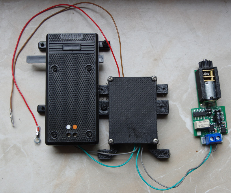
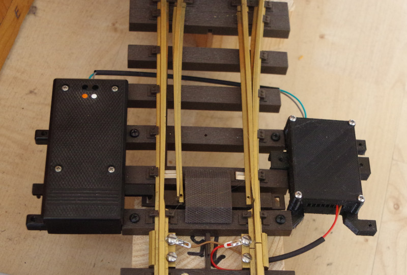
Or mounted opposite to the turnout drive on the turnout. The picture still shows the slightly smaller version G1:
Outdoor Variant
For operation in the garden (outdoor), after unsuccessful experiments with spray lacquer, we decided to completely encapsulate the electronics. It is a bit more expensive but still works even if the railway is underwater.
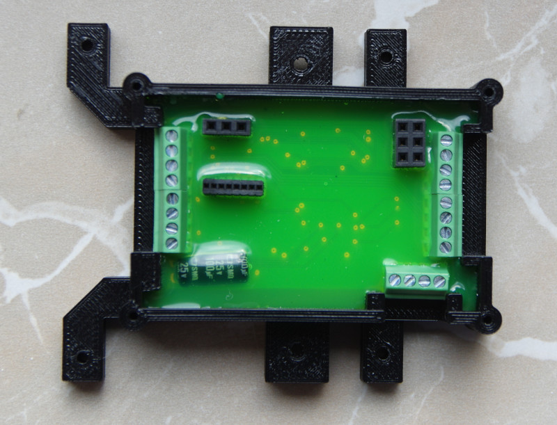
Closed, it looks like this:
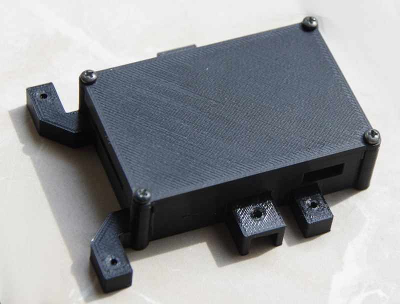
Here’s how we tested it:
Moisture Test
The CTC-Turnout Module-G, along with the LGB drive, was submerged while in the connected state (power turned on). Then both were removed from the water bath and moved on to the frost test.
Frost Test
The (still dripping wet) CTC-Turnout Module-G, along with the LGB drive, was stored in the freezer for several days and then immediately put back into operation. The turnout module worked right away; the LGB drive had to be freed mechanically – it was frozen.
Version G1 without screw terminals
Available only on special request.
Installation Version G1 in LGB Turnouts
Attention, this installation option raises the LGB drive by approx. 6 mm.
Available only on special request.
Unfortunately, there are at least some locomotives (including the LGB cog locomotive HGe 2/2) that then get stuck on the turnout drive.
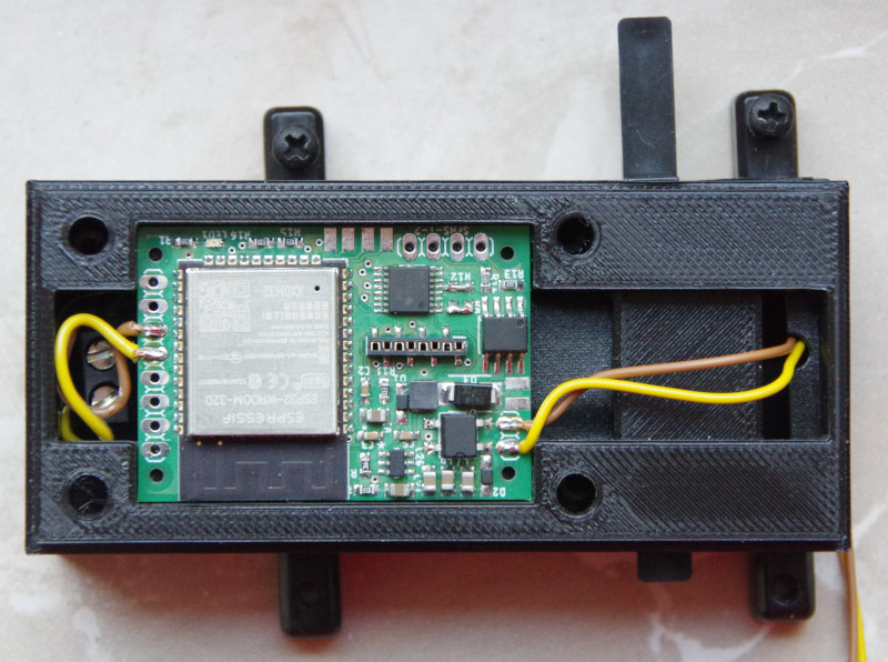
Connection
- Connect the shorter cables (HB-1 and HB-2, left in the picture) to the screw terminals of the LGB turnout drive.
- Connect the longer cables (Track-A and Track-B, right in the picture) to the track.
- If a turnout lantern is present, connect its minus pole to GND and the plus pole to HB-3.
Additional Connections
All other connections remain unused in this variant.
Installation Version G1 in Piko G Turnouts
Attention, this installation option raises the Piko drive by approx. 6 mm.
Available only on special request.
Unfortunately, there are at least some locomotives that then get stuck on the turnout drive.
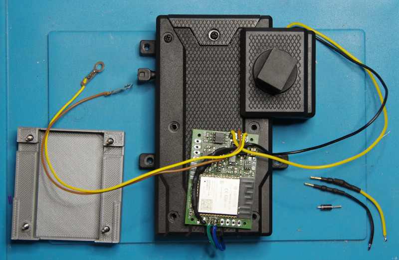
Connection
- Connect the shorter cables (HB-1 and HB-2, bottom in the picture, green and blue) to the screw terminals of the Piko turnout drive.
- Connect the longer cables (Track-A and Track-B, top right in the picture, yellow and brown) to the track.
- If a turnout lantern is present, connect its minus pole to GND (top left in the picture, yellow) and the plus pole to HB-3 (bottom in the picture, black).
Additional Connections
All other connections remain unused in this variant.
