Contents
1. Introduction and Outlook2. Reset and Install Turnout and Locomotive Modules, Install IR Balises
3. Construction of the Layout
4.1. Configuration of the Turnout Modules: Getting Started
4.2. Configuration of turnout modules: Connecting the turnout
4.3. Configuration of the turnout modules: Connect the semaphore signal
5. Create Track Plan
6. Starterkit with modules installed in locomotives and turnouts
6.1. First Commissioning of the Layout
7.1. Turnout Module Configuration: Connecting IR-Balises
7.2. Configuration Turnout Module: Assign Action to IR-Balises
8. Train Operation with BR365 and E103
9. Calibrate Sensor
10. Automating Train Operation
10.1. Automate Train Operation with One Locomotive
10.2. Automating Train Operation with One Locomotive, Second Version
10.3. Automate Operations with Shuttle Train Service
10.4. Automating Train Operations with Two Locomotives
1. Introduction and Outlook
Introduction
A starter set from CTC, in conjunction with an extension set, allows the assembly of a small track layout, with which the essential skills and capabilities of CTC can be tested and used. Although this is “just” a starter set, the layout is built in such a way that it can be expanded. These extensions will be described in the course of additional documentation. The construction of the starter set takes into account the extensions already in the assigned names, and this will be pointed out at the relevant points.
This document describes the starter set plus extension set for Märklin C track. The modules must be installed and configured into the locomotives and turnouts. If a starter set is used with already built-in CTC locomotive and turnout modules, the steps for installation can be skipped. Additionally, two semaphore signals with magnetic drive are used. The following topics will be covered initially:
- Installation and electrical connection of modules (locomotives, turnouts) (Chapter 2),
- Layout construction (Chapter 3),
- Configuring turnout modules for the operation of turnouts and semaphore signals (Chapter 4),
- Creating the track diagram (Chapter 5), and
- First commissioning of the layout (Chapter 6).
The layout to be built is similar to the one described in the article A CTC Model Railway is born. The associated application software, CTC-App, can be installed and run under both Windows, Linux, and Mac. Possible limitations regarding the operating systems must be considered. The various Linux distributions can indeed show divergent behavior. More information about the supported versions can be found in the Operator’s manual Chapter 2.
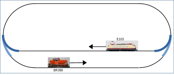
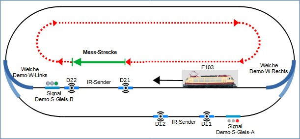
The layout floor plan consists of an oval with a station as a stop. For the train operation, it is assumed that one locomotive runs clockwise and another locomotive runs counter-clockwise. With the CTC-App, the turnouts are switched, and the locomotives are driven.
Once the locomotives have been run on the layout for the first time, the expansion of the layout can commence:
- Build in IR balise (formerly called “IR transmitter”) into the tracks and configure for operation (Chapter 7),
- Supplement track plan with IR balise (Chapter 7),
- Calibrate the locomotive sensors (Chapter 9), and
- Carry out train operation with signals and IR balise (Chapter 10).
The following functionality is implemented: when a signal is set to “stop”, the locomotive slows down, travels up to the IR balise in front of the signal and stops. The functionality is expanded to include the balise.
For the designations of the balise, signals and turnouts, names are chosen that are useful or even necessary for block operation and train automation (detailed explanation see “Outlook”).
Following this, automated train operation is introduced. With this configuration, a small “timetable” is created for one locomotive:
- Entry into the station area with the locomotive slowing down (Chapter 10).
- Slow travel into the station and stopping (Chapter 10).
- After the predefined waiting time, the locomotive continues its journey, travels a lap and again enters the station area (Chapter 10).
Outlook
For further expansion of the layout, the starter set will be extended:
- A turnout and further tracks will enable a “terminal station”.
- The block operation will be expanded with additional IR balises.
- Some blocks will receive semaphore signals.
- Appropriate CTC modules are required for the IR balises, semaphore signals and the turnout.
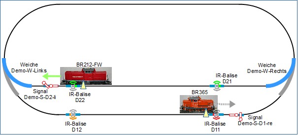
With the help of the mentioned expansions, the operation will be extended to the terminal station. The following illustration shows the schematic track diagram in a very extensive expansion phase. It will be indicated which of the individual balises, signals, turnouts, and tracks are used in the respective setup examples.
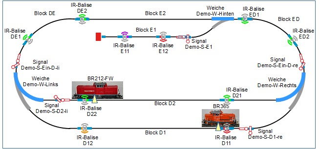
Names are chosen for the designations of the tracks and blocks, as well as for the balises, signals, and turnouts, which are meaningful or even necessary for block operation and train automation.
- There are two station areas, these are designated with “D” and “E”. This results in the following blocks:
- Block D1 is the “throughway area” of “station area D”.
- Block D2 is the “stop area” of “station area D”.
- Block E1 is the “stop area” of “station area E”, this station is designed as a terminal station.
- Block E2 is the “throughway area” of “station area E”.
- Block DE connects Block D with Block E. The naming adopts the direction of a locomotive in a clockwise direction.
- Block ED connects Block E with Block D. The naming adopts the direction of a locomotive in a clockwise direction.
- Balises are numbered in a clockwise direction and assigned to a block.
- Balises D21 and D22 belong to Block D2 and are closely related to the position of the corresponding signal Demo-S-D2-li.
- Balises D11 and D12 belong to Block D1 and are closely related to the position of the corresponding signal Demo-S-D1-re.
- Balises DE1 and DE2 belong to Block DE and are closely related to the position of the corresponding signal Demo-S-Ein-D-li.
- Balises ED1 and ED2 belong to Block ED and are closely related to the position of the corresponding signal Demo-S-Ein-D-re.
- Balises E11 and E12 belong to Block E1. Balise E12 is closely related to the position of the corresponding signal Demo-S-E1.
- Signals, like balises, are part of a block. Signals can be seen as “exit signals out of a block”
or as “entry signals into the next block” (in the direction of the moving train).
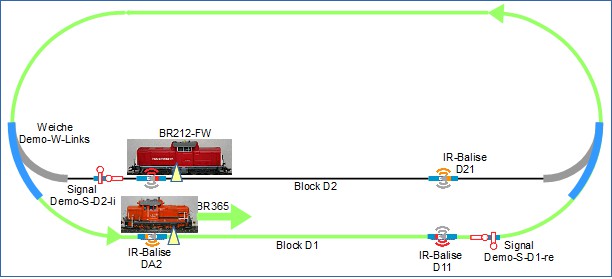
- Signal “Demo-S-D2-li” is an exit signal for Block D2, locomotive BR212-FW travels in a clockwise direction and later in a shuttle train operation.
- Signal “Demo-S-D1-re” is an exit signal for Block D1, locomotive BR365 travels counter-clockwise.
2. Reset and Install Turnout and Locomotive Modules, Install IR Balises
This chapter covers the following topics:
- Resetting turnout modules,
- Installing turnout modules into Märklin C-track turnouts,
- Installing locomotive modules, and
- Installing IR balises into Märklin C-track.
Basics
Whenever you are not 100% sure how a module is configured, you should reset it before connecting anything to the module!
Always - and it is important to emphasize: ALWAYS - before a CTC turnout module or a CTC-IO module is installed and wired anywhere, it must be reset. “Reset” in this context means that it must have an “empty” configuration.
This avoids unintended, undesirable, and potentially harmful control and switching states. These could, for instance, originate from a previous different configuration and wiring that made sense for that setup back then but is now no longer required or desired and may even be damaging. An improper configuration can lead to the destruction of CTC modules or other switching elements.
Note: Modules newly delivered by CTC always come in a reset state, meaning you do not need to do anything for these.
Reset Configuration of the Turnout Modules
For simplicity, it is recommended to reset each CTC turnout module individually. CTC turnout modules and CTC-IO modules are reset as follows before installation and wiring of the track system:
- The module to be reset is supplied with operating voltage.
- The CTC app is started.
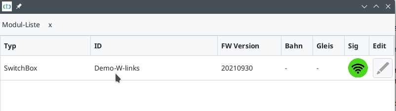
- In the start window, the “Module List” tab shows the list of all modules. Since only one CTC turnout module is supplied with operating voltage, the list contains only one entry.
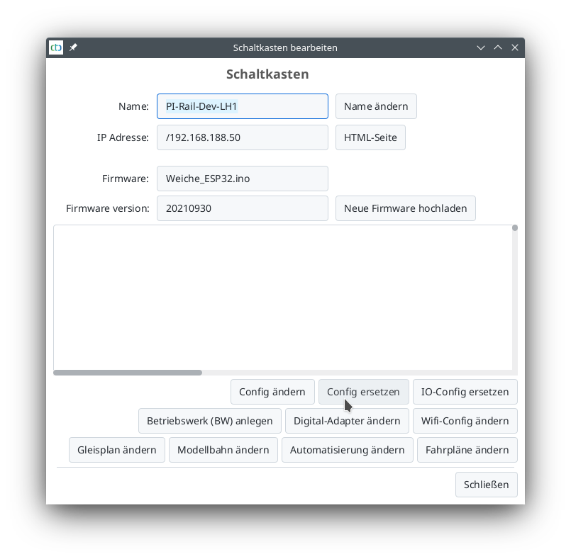
- Click on the pencil icon in the Edit column in the row of the module to be reset.

The “Switch Box” window opens. Click on the “Replace Config” field.
The “Select Config” window opens:
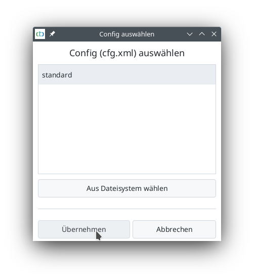
- Select the “standard” configuration there.
- Then click on “Apply.”
A notice with information about the selected configuration follows:
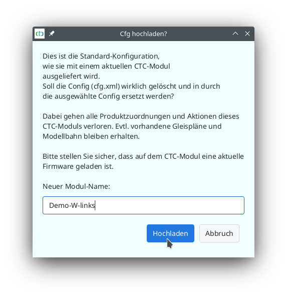
- Give the module to be deleted a new name. In the example, this is initially done for the CTC turnout module to be installed in the left turnout. The name “Demo-W-left” is given.
- Click on the “Upload” button.
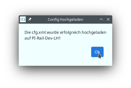
The old configuration is deleted, and the successful upload to the module with the previous module name is confirmed:
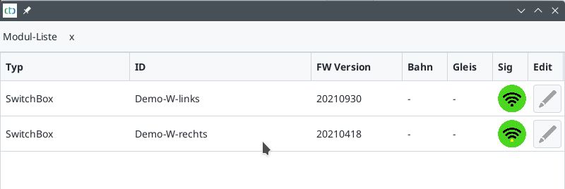
The newly assigned name is now already shown in the module list:
The second turnout module is reset in the same way:
- The power supply is turned off.
- The second turnout is connected.
- The power supply is turned on again.
- The CTC app is restarted.
- The second CTC turnout module is reset just like the first one. Since it is the module for the right turnout, the name “Demo-W-right” is assigned.
- Both CTC turnout modules are now reset to a known and defined initial state and have a new unique name.
Both turnout modules are reset and connected to the power supply. The CTC app is restarted and shows the newly assigned names:
Note that resetting the configuration does not delete the track plan stored in a module. If a track plan is stored in a module, it remains when resetting.
Install Turnout Modules
The CTC turnout modules in this starter set are used for the following functions:
- The control of the electromagnets of the turnouts,
- The control of a semaphore signal with magnetic spool drive (note: NOT a light signal but a mechanical signal), and
- Two IR balises.
Each turnout has its own CTC turnout module.
The CTC turnout modules must be installed in the turnouts. It is important to note the module names assigned when resetting the turnout modules:
- The module “Demo-W-left” is installed in the turnout used on the left in the track plan and is a “left-turnout.”
- The module “Demo-W-right” is installed in the turnout used on the right in the track plan and is a “right-turnout.”
Further information on switching with CTC modules can be found here:
Overview of Switching with CTC.
Instructions for installing or converting turnouts for the C-track are here:
Conversion of Märklin C-Track Turnout
Install Locomotive Modules
The CTC modules for the locomotives fulfill the following functions:
- Motor control of the locomotive,
- Light in the direction of travel of the locomotive and rear light,
- Infrared reception, and
- Control of the mechanism for uncoupling (if present in the locomotive).
Each locomotive has its own CTC locomotive module.
The CTC modules for the locomotives must be installed in the locomotives. Links to this are here:
Overview of CTC Locomotive Modules.
Install IR Balises
The IR balises must be installed in the tracks. Instructions for this are here:
The individual modules are installed, and the track system can be set up.
3. Construction of the Layout
This chapter describes how
- the track layout is constructed
- the semaphore signals and the IR balises are connected to the turnout modules.
Starter Set Construction of the Track Layout
The layout plan consists of an oval with a stop, like a small station. The setup is constructed and the semaphore signals and IR balises are connected to the configured turnout modules. For the CTC starter set described here, two CTC locomotive modules and two CTC turnout modules are needed. Further chapters will describe how to build the track diagram “on the PC” using the CTC app. Subsequently, the setup will be “put into operation” and train operations will take place. It is assumed that one locomotive travels clockwise and another locomotive travels counterclockwise.
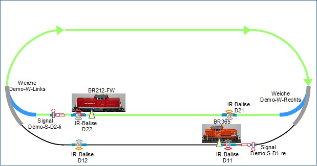
The layout is schematically represented in the following figure.
For constructing the track oval with the passing or station track, the following turnout and track material is used:
- Left curved turnout Article No. 24771 equipped with electric drive Article No. 74491
- Right curved turnout Article No. 24671 equipped with electric drive Article No. 74491
- 10x curved track R1, 30°
- 2x curved track R2, 30°
- 12x straight track 188.3 mm, of which 4 are retrofitted with CTC IR balises
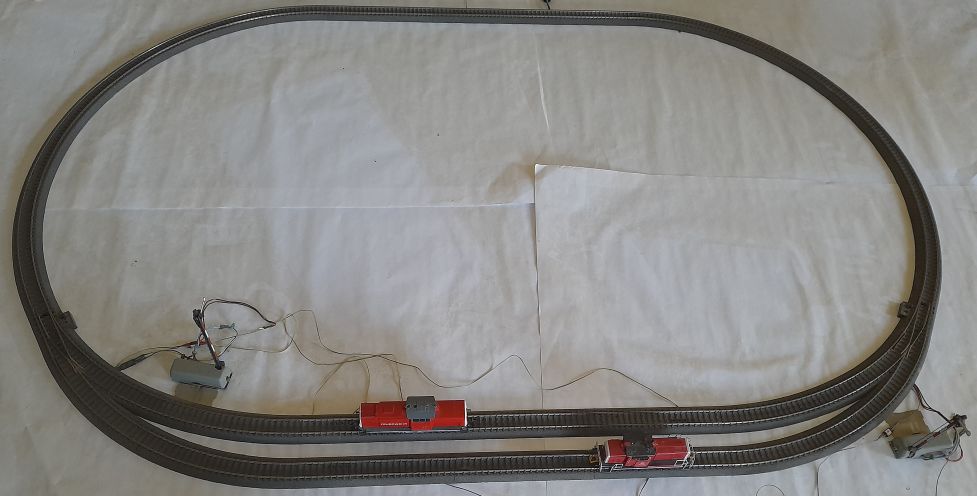
Top view of the layout, when it is assembled with the turnouts and tracks and the locomotives are placed on it:
The semaphore signals and IR balises will be connected next.
Connecting Semaphore Signals
The semaphore signals intended in this description have a magnet drive. The CTC turnout module used has a connection “W1”, this is used for the turnout drive and is already connected. The connection “W2” is used for the semaphore signal. The corresponding connector is designed as a three-pole linear socket connector. The operating voltage is applied to the central socket, the two outer connections are the switching functions. The magnet drive of the semaphore signal is to be connected accordingly.
| Label on Module | Output Function | Cable Color | Shrink Tube / Connector Color | Socket Position | Function on Semaphore Signal |
|---|---|---|---|---|---|
| W2-Red | Switch-1 | blue | red | Left | Magnet for switch state Hold |
| W2-VBB | Drive power supply | yellow | yellow | Center | Power supply |
| W2-Green | Switch-2 | blue | green | Right | Magnet for switch state Go |
Connecting IR Balises
Each of the CTC turnout modules controls two IR balises (infrared balises) in the starter set. The connection of IR balises to the turnout module is made according to the following table:
| Label on Module | Output Function | Shrink Tube Color | Socket Position | Function on IR Balise |
|---|---|---|---|---|
| IR1-GND | IR Balise 1 GND | green | Center-Left | IR Balise 1 Diode Cathode |
| IR1-VCC | IR Balise 1 VCC | red | Left | IR Balise 1 Diode Anode |
| IR2-VCC | IR Balise 2 VCC | red | Right | IR Balise 2 Diode Anode |
| IR2-GND | IR Balise 2 GND | green | Center-Right | IR Balise 2 Diode Cathode |
Further information on the setup and connection of IR balises to the turnout module can be found here:
The track layout is now constructed and the turnout modules can be configured.
4.1. Configuration of the Turnout Modules: Getting Started
Resetting the Configuration of CTC Turnout Modules
To be independent from any default settings and previous configurations, the CTC turnout modules are reset to their original state. This also applies to CTC Multi-IO modules, although these are not used in the starter set here.
Note: Whenever you are not 100% sure about how a module is configured, you should reset it before connecting anything to this module! Newly delivered modules from CTC are always in a reset state, i.e. with these, you don’t need to do anything.
The resetting of the CTC modules should have already been done, here is the corresponding chapter once more:
Installation of the Turnout Modules and Locomotive Modules.
First Steps to Configuring the CTC Turnout Modules
This text describes the first steps in configuring the turnout modules for the starter set “Locomotive and Turnout”. It is assumed:
- the track system is set up,
- the turnout modules are built into the turnouts and the magnetic drives are connected,
- the signals are wired to the turnout modules (but will only be configured later),
- the IR balises are wired to the turnout modules (but will only be configured later) and
- the power supply is complete.
The wiring of the signals and the IR balises for each of the turnout modules is carried out as follows:
The wiring has been carried out, now it is time to inform the respective CTC turnout module, which “products” (turnout drive, semaphore signal and IR balises) are connected to which port of the module and how they are driven. When we talk about “connections” in the following, we do NOT mean electrical cables, but connections at software level.
The following steps are described and carried out in detail:
- “Products” are taken from the product catalogue. For each turnout module, the product catalogue includes
- one turnout,
- one semaphore signal and
- two IR balises.
- These products have “connections” that require a certain drive, this information is already included in the
product catalogue and is used by the CTC app to check for the correct connection:
- The magnetic drive of the turnout and the magnetic drive of the semaphore signal require a short pulse.
- The IR balises are driven with a pulse width modulated signal.
- The connections of the products are linked to the pins of the turnout module. The configuration of the turnout module is implicitly set according to the necessities for the drive of the respective product.
First Steps of Configuration
In the next step, the electrical connections must be communicated to the turnout modules. Connected to each turnout module are:
- the magnetic drive of the turnout
- the magnetic drive for a wing or form signal
- two IR balises, one very close to the signal and the other further in front.
The configuration of the right turnout module is being carried out.
Click on “Settings” - “Configurator” in the CTC app to open the “List of all Modules” window.

In the table, under “Type”, there are two modules of the type “SwitchBox”. These are the two turnout modules, which need configuring. During the reset, new names were already assigned, and these can be found in the “ID” column.
Alternatively, you can reach the “Edit Switch Box” window directly from the CTC app under the “Modules” tab:
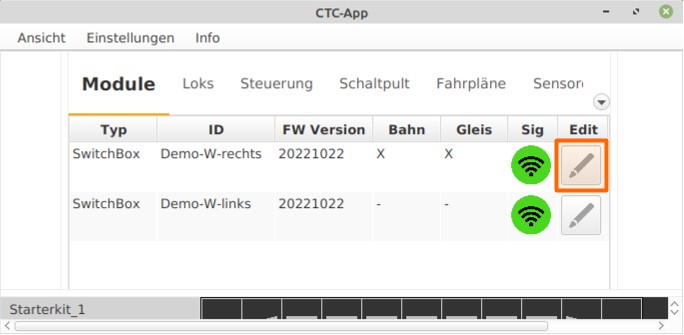
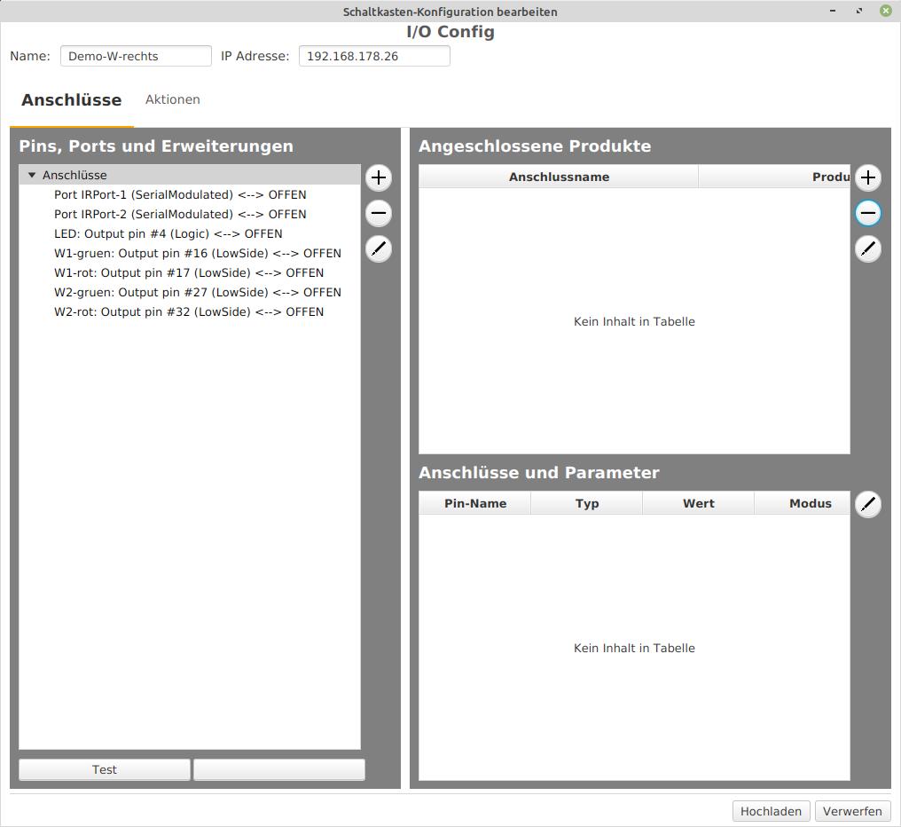
Clicking on “Edit” in the respective row of the “SwitchBox” list selects “Demo-W-right”. The “Edit Switch Box” window opens.
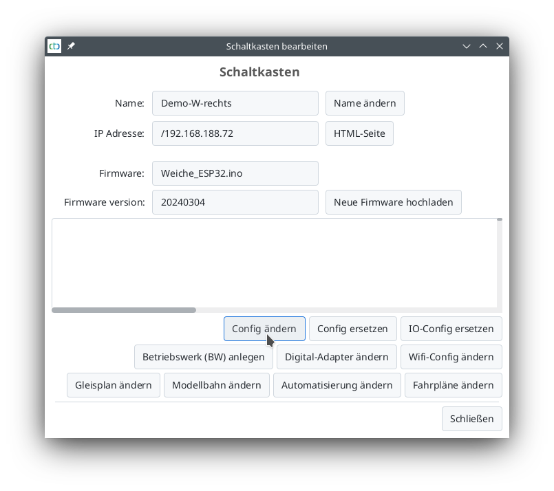
Clicking on “Change Config” opens the configuration window “Edit Switch Box Configuration”. The connection and function of the magnetic turnout drive are checked as follows:
- In the field “Pins, Ports, and Extensions” select the output “W1-green”.
- Click on the “Test” field. The turnout switches.
- In the field “Pins, Ports, and Extensions” select the output “W1-red”.
- Click on the “Test” field. The turnout switches.
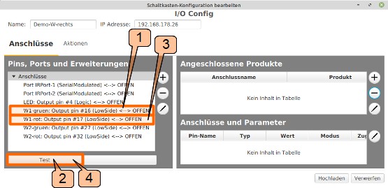
Now, the turnout has switched at least once, and it is known which connection switches the turnout to “straight” and which to “turn”. This information is needed for the correct connection of the turnout.
4.2. Configuration of turnout modules: Connecting the turnout
This text describes the configuration of turnouts modules for the starter set. The following is assumed:
- the track installation is set up,
- the turnover modules are built into the turnouts and the coil drive of the turnouts is wired,
- the signals are wired to the turnout modules,
- the IR balises are wired to the turnout modules,
- the power supply is complete,
- the turnout modules have been reset,
- the turnout drives are wired, and
- the semaphores are wired.
For your reference: The wiring for each of the turnout modules is carried out as follows:
Connecting the Turnout Product (magnetic) “Demo-W-right”
To connect the magnetic drive of the turnout to the turnout module (in terms of software connection), the configuration is called up:
- Click on the “Edit” icon in the line of “Demo-W-right” under the “Module” tab.
- The “Edit Junction Box” of the turnout module window will open.
- Click on the “Change Config” field.
- The “Edit Junction Box Configuration” window will open.
A turnout product is connected to the “W1-green” and “W1-red” terminals of the “Demo-W-right” module. When selecting the product to be connected next, it should be noted that it is a turnout that veers to the right in the direction of travel.
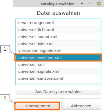
In the “Edit Junction Box Configuration” window, click on “+” in the “Connected Products” section to open the list of product catalogs and select a catalog.
- Select the catalog “universal-turnouts.xml” and
- Open it by clicking on “Apply” for further work.
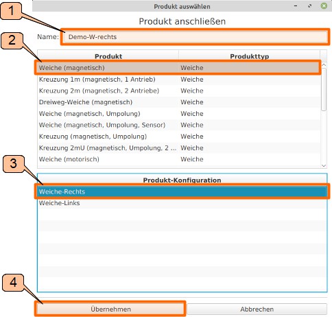
The “universal-turnouts” catalog is selected. From this catalog a name is assigned and a turnout is selected:
- Enter “Demo-W-right” as the product name in the “Select Product” window.
- The “Turnout (magnetic)” is selected as the product.
- “Turnout-Right” is selected for Product Configuration.
- Click on “Apply” to confirm the selection.
The CTC turnout module is already built into the turnout, and W1 is wired with the magnetic turnout drive. Now it’s time to make “the logical wiring” of the control. Knowing which pin / port of the turnout module switches the turnout to “turn” or “straight” is a prerequisite for this. The procedure is as follows:
- Select the “W1-green” output in the “Pins, Ports and Extensions” field.
- Click on the “Test” field. The turnout switches. Assumption: the turnout switches to “straight”
- Select the “W1-red” output in the “Pins, Ports and Extensions” field.
- Click on the “Test” field. The turnout switches. Assumption: the turnout switches to “turn”.
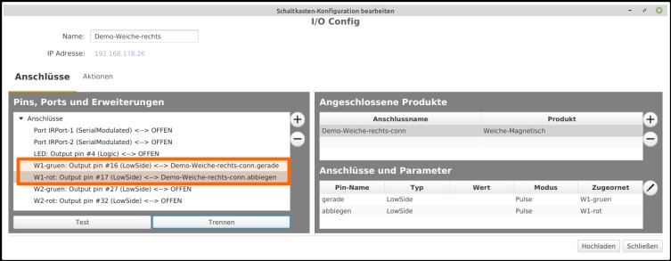
The pin names (“straight” and “turn”) mentioned in the “Connections” window of the product (“Demo-Turnout-right-conn”) are now connected with the connections mentioned in the “Pins, Ports and Extensions” window:
- Clicking on “W1-green: Output pin #16 (Low Side)” selects the pin of the turnout module.
- Click on “straight” under “Connections and Parameters” selects the pin name “straight” of the product.
- Click on “Connect” establishes the logical connection between “W1-green” and “straight”.
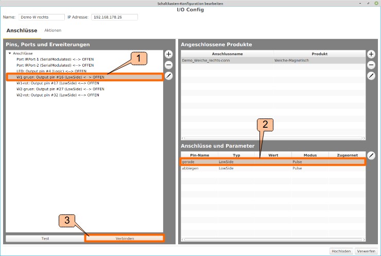
“W1-red: Output pin #17 (Low Side)” is also connected to “turn”.
- Click on “W1-red: Output pin #17 (Low Side)” selects the pin of the turnout module.
- Click on “turn” under “Connections and Parameters” selects the pin name “turn” of the product.
- Click on “Connect” establishes the logical connection between “W1-red” and “turn”.
The result of the connection work of the turnout module to the magnetic turnout drive looks like this in the CTC app:
In the “Edit Junction Box Configuration” window, the action is completed by saving the configuration in the turnout module “Demo-Turnout-right” by clicking on “Upload”.
Connect the Product Turnout (magnetic) “Demo-Turnout-left”
For the second turnout, proceed similarly as described above. The configuration is called up with “Edit” from “Demo-Turnout-left”.
- Unlike “Demo-Turnout-right”, for “Demo-Turnout-left” in the “Connect Product” step, the product configuration “Turnout-left” should be selected.
The switching connections are tested and established as described above. In the “Switchbox Configuration Edit” window, the action is completed by clicking on “Upload” to save the configuration in the turnout module “Demo-Turnout-left”.
4.3. Configuration of the turnout modules: Connect the semaphore signal
This text describes the configuration of the turnout modules for the starter set. It is assumed that:
- the railway track has been constructed,
- the turnout drives are wired,
- the turnout modules are reset and the names have been assigned (Demo-turnout-left, Demo-turnout-right),
- the signals are wired to the turnout modules,
- the IR balises are wired to the turnout modules (the IR balises will not yet be needed for the time being) and
- the power supply is complete.
To recap: The wiring for each of the turnout modules is carried out as follows:
#
Connecting Product Semaphore Signal (magnetic) to Demo-Turnout-right
The magnetic drive for the semaphore signal is connected in a very similar way to the magnetic drive for the turnout.
To connect the magnetic drive of the semaphore signal to the turnout module (link them from a software perspective), the configuration is accessed as follows:
- In the “Modules” tab, click on the “Edit” icon in the row of “Demo-Turnout-right”.
- The “Edit Control Box” window of the Demo-Turnout-right will open.
- Click on the “Change Config” field.
- The “Edit Control Box Configuration” window opens.
In the “Edit Control Box Configuration” window, click on “+” in the “Connected Products” area to open the list of product catalogs.
- Select the catalog “universal-signals.xml” and
- click on “Apply” to proceed with further tasks.
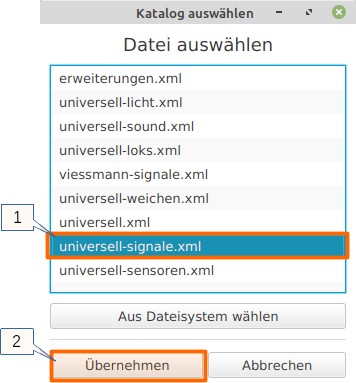
The “universal-signals” catalog is selected. From this catalog, a name is assigned and a signal is selected. The information “right” or “left” refers to the direction of travel (clockwise) that the signal should apply to (“right” means “clockwise”):
- Enter “Demo-S-Track-A” in the “Name” field
- “Semaphore Signal (magnetic)” is selected as Product
- “Semaphore Signal right” is chosen as the Product Configuration and
- by clicking on “Apply”, the semaphore signal is ready for connection.
.jpg)
After clicking “Apply”, you will return to the “Edit Control Box Configuration” window.
As with the connection of the turnout control, “w2-green: Output pin #27 (Low Side)” or “W2-red: Output pin #32 (Low Side)” is selected and its function is tested by clicking “Test”. Assumption: At “W2-green” the semaphore signal switches to “free ride” and at “W2-red” the signal switches to “halt”. The connection of the semaphore signal is carried out in a manner similar to the magnetic turnout drive:
- Select “W2-green: Output pin #27 (Low Side)” in the “Ports” section,
- choose “green” under “Connectors”, and
- click “Connect”.
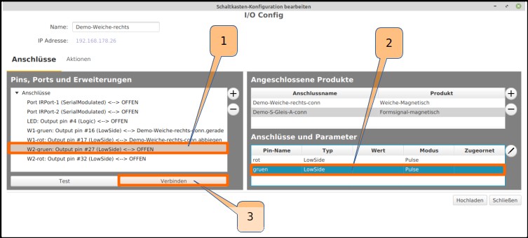
Just as the “W2-green” pin was connected to the “green” connection, the “W2-red” pin is also connected to the “red” connection. The semaphore signal, like the turnout drive, is now completely connected:
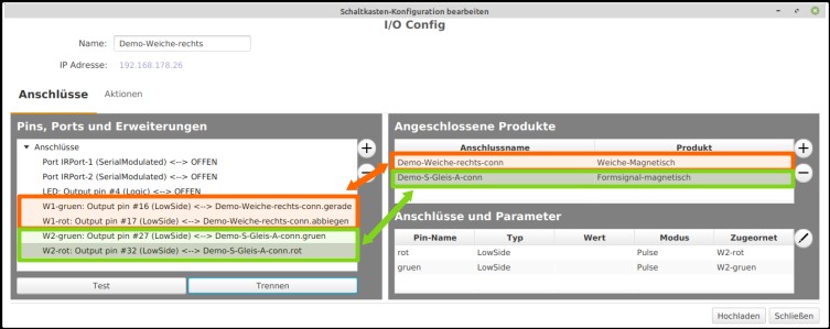
In the “Edit Control Box Configuration” window, the action is completed by uploading the configuration to the turnout module “Demo-Turnout-right” with a click on “Upload”.
Connecting the Semaphore Signal (magnetic) to the Demo Turnout-Left
For the semaphore signal, which is connected to the Demo Turnout-Left, proceed in a similar manner as described above. Use the “Edit” of “Demo Turnout-Left” to call up the configuration. In the further course, this signal is given the name “Demo-S-Track-B”. In the “Switch box configuration edit” window, the action is completed by clicking on “Upload” to save the configuration in the turnout module “Demo Turnout-Left”.
The turnout modules are configured, the turnouts and semaphore signal switch.
5. Create Track Plan
At CTC, a hierarchy of model railway and track plan is assumed: A model railway consists of one or more track plans.
Both track plan (or track plans) and model railway are stored in one of the modules. This means that the track plan can be considered part of the configuration stored in a module. Here in the starter set, the track plan and model railway are stored in the turnout module “Demo-W-right”. To create and edit the track plan in this starter set, the module’s configuration is opened. There are two ways to do this:
- Select “Settings” - “Configurator” in the main menu. The new window “List of all modules” opens. In the row with the ID “Demo-W-right”, click on the pencil in the “Edit” column, the “Edit switch box” window opens.
- In the main menu, select the “Modules” tab. In the row with the ID “Demo-W-right”, click on the pencil in the “Edit” column, the “Edit switch box” window opens.
Clicking on the “Change track plan” button opens the “Edit track plan” window. Clicking on the “New track plan” button allows you to enter the name of the new track plan and confirm it with “Create”. Enter “Starterkit” as the name for the new track plan.
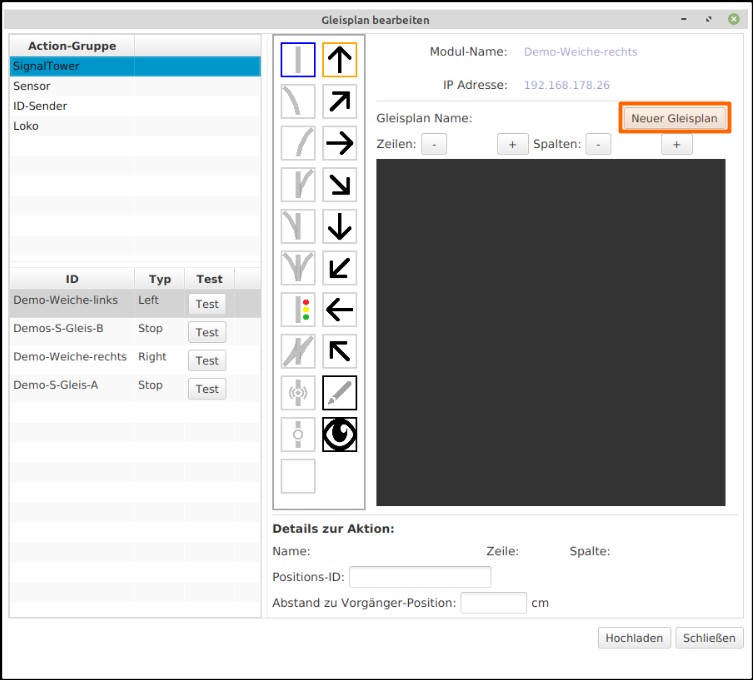
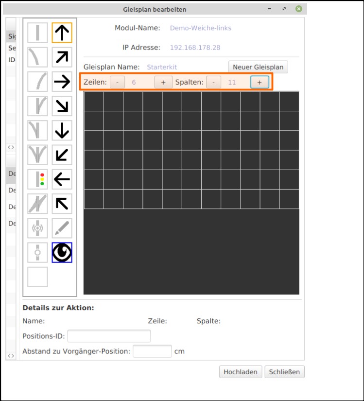
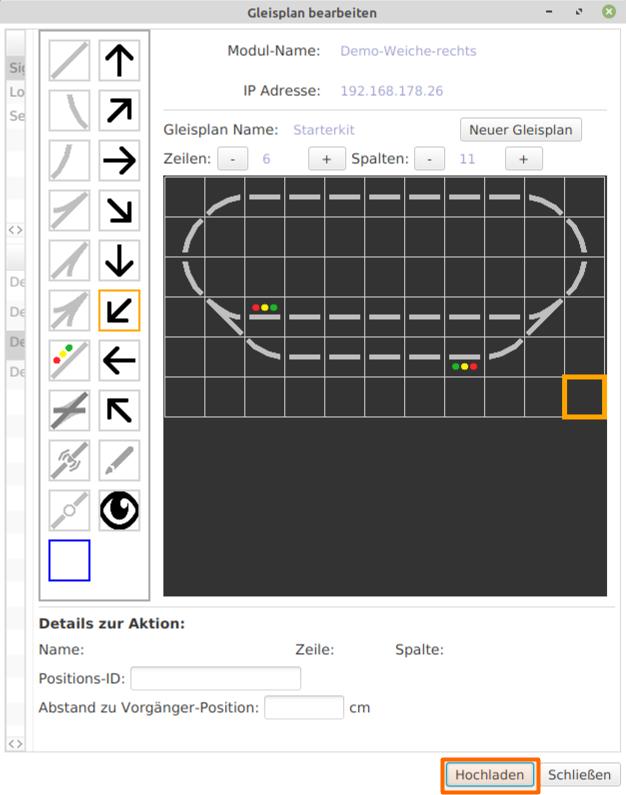
The track plan now has the new name “Starterkit”. The track plan has a “default size” of 10 x 10 elements. For the starter kit track plan, 6 x 11 elements are needed. The values for “columns” and “rows” need to be adjusted accordingly.
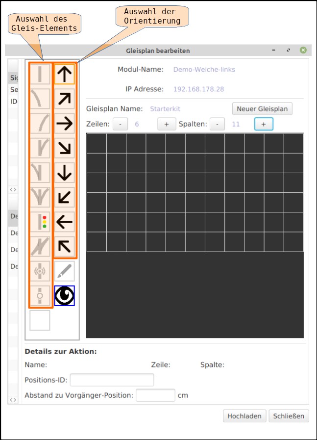
Individual track elements and their orientation are selected.
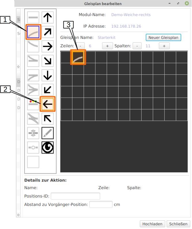
In this example, a track curve is positioned:
- Select “to the left” as the orientation,
- select “track curve” as the track, and
- position it on the track plan with a mouse click.
In this way, the track plan is created with additional track elements, turnouts, and semaphore signals. The IR-balises are not inserted into the track plan; this will be done later. A mouse click on “Upload” saves the created track plan in the module “Demo-turnout-right”.
Assigning Turnouts and Semaphore Signals in the Track Plan
The track plan is created; next, the turnouts and semaphore signals are assigned according to the following table:
| ID | Element in the Track Plan |
|---|---|
| Demo-W-left | left turnout in the track diagram (Demo-W-left) |
| Demo-W-right | right turnout in the track diagram (Demo-W-right) |
| Demo-S-Track-B | signal left in the track diagram (Demo_S_Track_B) |
| Demo-S-Track-A | signal right in the track diagram (Demo_S_Track_A) |
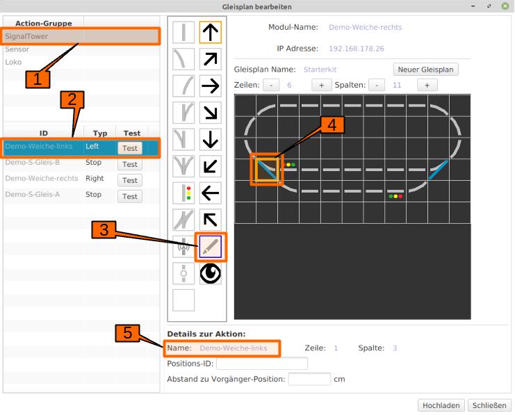
“Demo-W-left” is assigned as follows:
- Select “SignalTower” in the “Action Group” field.
- Select “Demo-W-left” in the “ID” column.
- Select the pencil.
- Select the left turnout in the track diagram.
- In “Action Details”, you can see that the turnout name “Demo-W-left” has been entered in the “Name” field.
The same procedure is followed for the right turnout:
- Select “SignalTower” in the “Action Group” field.
- Select “Demo-W-right” in the “ID” column.
- Select the pencil.
- Select the right turnout in the track diagram.
- In “Action Details”, you can see that the turnout name “Demo-W-right” has been entered in the “Name” field.
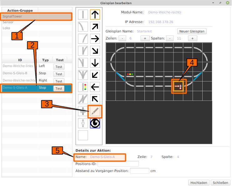
The right signal “Demo-S-Track-A” in track section “Block-A” is assigned very similarly to the turnouts as follows:
- Select “SignalTower” in the “Action Group” field.
- Select “Demo-S-Track-A” in the “ID” column.
- Select the pencil.
- Select the right signal in the track diagram.
- You can see in the track diagram how the symbol has changed.
- In “Action Details”, you can see that the semaphore signal name “Demo-S-Track-A” has been entered in the “Name” field.
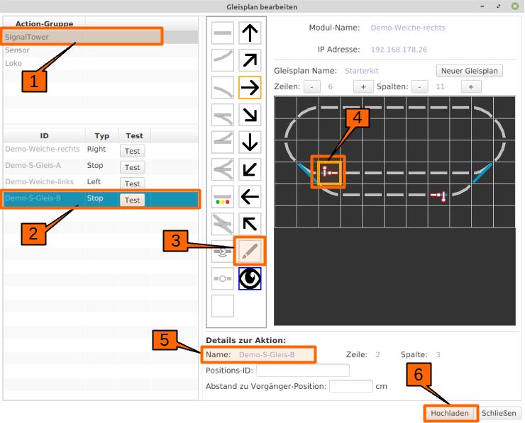
The same procedure is followed for the left signal “Demo-S-Track-B” in track section “Block-B”:
- Select “SignalTower” in the “Action Group” field.
- Select “Demo-S-Track-B” in the “ID” column.
- Select the pencil.
- Select the left signal in the track diagram. You can see in the track diagram how the symbol has changed.
- In “Action Details”, you can see that the semaphore signal name “Demo-S-Track-B” has been entered in the “Name” field.
- The track plan is now configured for the first test runs and is saved in the turnout module “Demo-turnout-right” with a click on “Upload”.
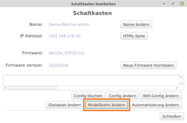
The last step is to integrate the track plan into the model railway. To do this, open the configuration of “Demo-turnout-right” again. Clicking on the “Change model railway” button opens the “Edit model railway” window. Clicking on “New track section” allows you to assign a new name. In “Available Panels,” the panel named Starterkit is selected and positioned by clicking on the “Arrow” button. Clicking on the “Upload” button saves the new model railway in the track module.
6. Starterkit with modules installed in locomotives and turnouts
This starter set consists of modules with a “Starter Set” configuration which are pre-installed in locomotives and turnouts.
CTC parts with configuration:
- 2 x locomotive with built-in and configured CTC-Locomotive Module-H0a: Motor configuration and one light.
- 2 x turnout with built-in and configured CTC-Turnout Module. Configuration: turnout, signal, 2x IR-Balise
- 2 x signal
- 4 x CTC-IR-Balise installed in four tracks
- 1 x CTC-Router
Additional necessary parts
- Power supply / power adapter
- 2 x Wing signal
- Rails
Starter-Set with Configured CTC Modules Installed in Locomotives and Turnouts
The following describes the construction and commissioning of a model railway with CTC control. It is assumed that a starter-set with CTC modules installed in locomotives and turnouts is available.
The details of the turnout module can be found here: CTC-turnout module.
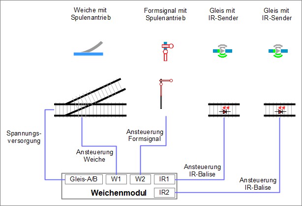
Each of the turnout modules is connected as shown in the following sketch:
- to Track-A/B the power supply for the turnout module,
- to W1 the turnout drive,
- to W2 the drive for the signal
- to IR1 a balise installed in the track, here referred to as DA1 and
- to IR2 a balise installed in the track, here referred to as DA2.
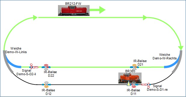
The track system is built according to this sketch.
The fully assembled system with the locomotives looks like this:
Now let’s proceed with the Creation of the track image
6.1. First Commissioning of the Layout
In the following, it is assumed that the CTC layout is set up and configured according to the descriptions for the starter set.
During the switch-on sequence of the CTC components, it must be noted that the Wi-Fi router must be switched on and ready for operation first. The railway layout is then switched on.
The CTC app finds the PI-Rail Wi-Fi and connects to the CTC modules. The configuration of the modules is read out. In the chosen example of the starter kit, the CTC app has found a locomotive (BR365), two turnouts, and two semaphore signals. The configuration of the locomotive was read out, which gives the respective image of the locomotive, its name, and further configuration information, which will be looked at later. The track plan - here called “Starterkit_1” - is stored in one of the configured turnout modules (Demo-W-right) and was also read out. It also contains information about the semaphore signals.
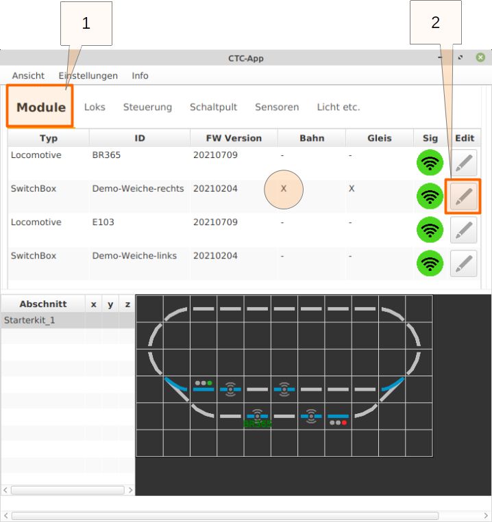
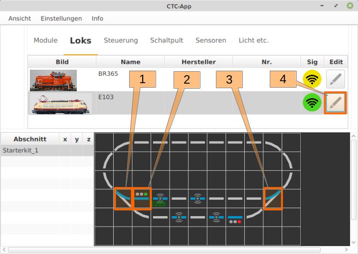
Once the CTC app is started, the initial screen shows the “Module” window:

The window with the tabs for the selection “Modules, Loks, Control, Control panel, and Sensors” allows access to the individual function groups:
- Modules: The list of all found modules and their most important parameters appears here. From here, their configuration can be directly called up.
- Loks: Here all found locomotives appear, the locomotive highlighted in grey is the selected locomotive (see also “Control”).
- Control: Here the control panel of the selected locomotive appears (see “Loks”).
- Control panel: Here are displayed the controllable modules of the track diagram that perform switching functions, i.e. turnouts, signals, etc. The track diagram also includes the IR balise markers.
- Timetables: Here, timetables for automated train operation are edited and called up.
- Sensors: Here all sensors are shown. In this case, each locomotive has an infrared sensor. The sensors receive the messages from the IR balises built into the track.
Through the menu bar, with “View” and “Show Left Panel,” an additional control panel is opened. The windows of the panels can be moved so that they are clearly visible. The selection of “Control” for the left panel and “Control panel” for the right panel results in:
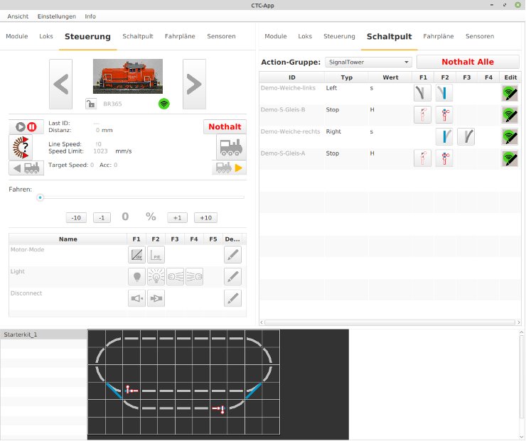
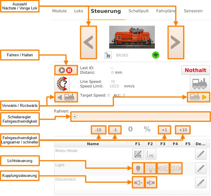
The “Control” tab offers control over the selected locomotive (in “Loks” selection tab):
The “Control Panel” tab provides access to turnouts and signals (and optionally other drives if available).
The switching functions are performed with the individual switches as follows:
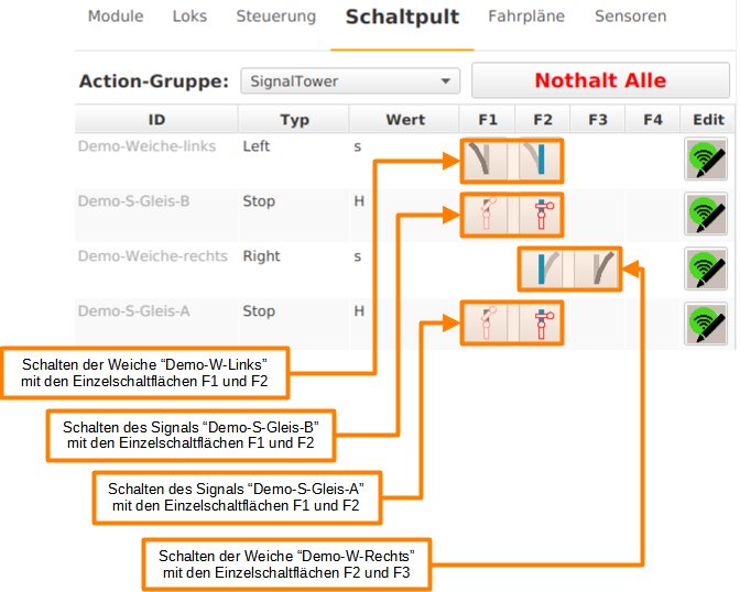
Turnouts and signals can alternatively also be switched directly in the track diagram:
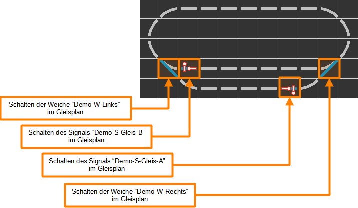
On the first operation of the layout, the BR365 locomotive can now run, the control of the turnouts allows the entry into the station track or the ride on the passing track. Also, the signals can be switched. It is noticeable that the locomotive does not react to the position of the signals, the train must be stopped manually in the “Control” window or the continuation of the journey has to be initiated.
Further configuration steps are necessary for the locomotive to slow down in front of a signal set to “Stop” and come to a standstill. The IR balises are used for this.
7.1. Turnout Module Configuration: Connecting IR-Balises
This text describes the configuration of the turnout modules for the starter set. In choosing words, note:
- “Wiring” refers to the electrical connection, that is, the cables, lines, connectors.
- “Connection” or “connecting” refers to the software-technological connection, that is, the configuration of the module to which the respective component (turnout with coil drive, semaphore with coil drive, IR-balises) is wired.
It is assumed:
- the track layout is set up,
- the turnout modules are installed in the turnouts and the coil drive of the turnouts is connected,
- the signals are wired to the turnout modules,
- the IR-balises are wired to the turnout modules,
- the power supply is complete,
- the turnout modules have been reset,
- the turnout drives are wired and
- the semaphores are wired.
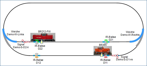
As shown right at the start, this is the track layout:
As a reminder: The wiring for each of the turnout modules is carried out as follows:
Applied to the track layout, this means for the wiring:
- The semaphores “Demo-S-D2-li” as well as the balises “D21” and “D22” are wired to the module of the turnout “Demo-W-Links”.
- The semaphore “Demo-S-D1-re” and the balises “D11” and “D12” are wired to the module of the turnout “Demo-W-Rechts”.
The “wirings” of the IR-balises are now being “connected”.
#
Connecting the IR Balise Product
In the “Modules” window, click on the “Edit” symbol for the ID “Demo-turnout-left”, the “Edit Switchbox” window will open. In the “Edit Switchbox” window, the “Edit Switchbox Configuration” window is opened by clicking on the “Change Config” button:
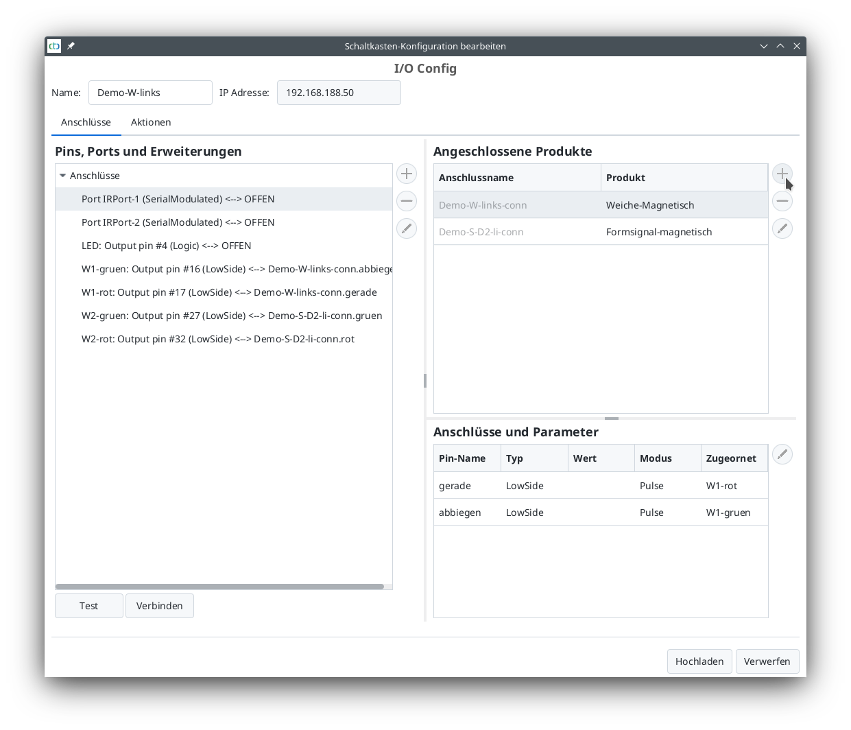
Here, in the “Connected Products” section, click on “+” (see mouse pointer) to open the list of product catalogs.
- The “universal-sensors.xml” catalog is selected and
- opened for further work by clicking on “Apply”.
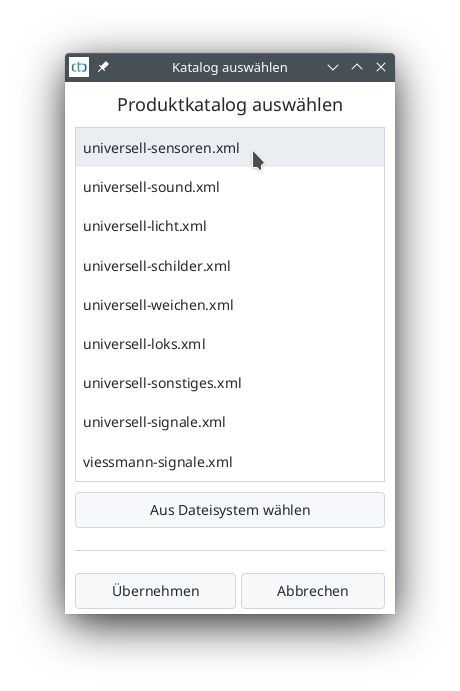
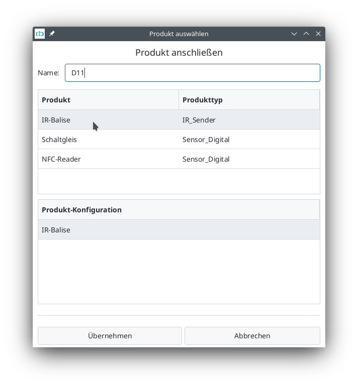
The “universal-sensors” catalog has been selected. From this catalog, the “IR-Balise” is selected and named:
- Enter “D11” for “Name”
- Select “IR-Balise” as the product and
- Click on “Apply” to prepare the IR-Balise for connection.
After clicking on “Apply”, you will be returned to the “Edit Switchbox Configuration” window.
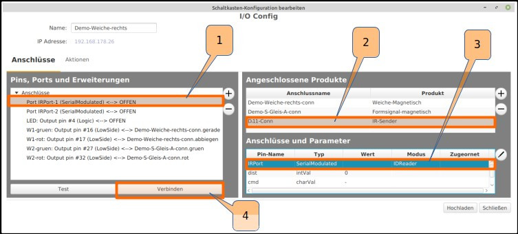
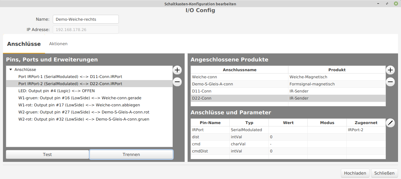
The first IR-Balise D11 will be connected:
- Select “Port: IRPort-1 (SerialModulated)” under “Pins, Ports and Extensions”,
- “D11-Conn” is selected under “Connected Products”,
- “IRPort-1” is selected under “Connections and Parameters”, and
- Click “Connect” to confirm the connection.
The same is done with the second infrared port “IRPort-2:
- Double-click to open the “universal-sensors.xml” product catalog,
- Select IR-Balise product,
- Enter “D12” as the name and confirm.
- In the “Edit Switchbox Configuration” window, select “Port: IRPort-2 (SerialModulated)” under “Pins, Ports and Extensions”,
- “D12-Conn” is selected under “Connected Products”,
- “IRPort-2” is selected under “Connections and Parameters”, and
- Click “Connect” to confirm the connection.
The first turnout module named “Demo-turnout-right” is now fully connected and has the following connected:
- a magnetic turnout drive,
- a magnetic signal drive,
- an IR-Balise D11, and
- an IR-Balise D12.
7.2. Configuration Turnout Module: Assign Action to IR-Balises
This text describes how to configure the turnout modules to assign an action to the IR-balises. It is assumed:
- the track layout is set up,
- the signals are wired to the turnout modules,
- the IR-balises are wired to the turnout modules,
- the power supply is complete,
- the turnout modules have been reset,
- the turnout drive is connected and
- the IR-balises are connected.
As a reminder: The wiring for each of the turnout modules is done as follows:
So far, the following has been completed:
- The wiring is done and
- the “products” (turnout drive, semaphore signal, and IR-balises) are connected to their respective ports/pins on the module.
Assign Action to IR-Balise
Basic Idea
The basic idea for the following configuration is: When a locomotive approaches a signal, it should receive information whether the signal is set to “Stop” or “Go” and how far the locomotive is from the signal. This information is sent to the locomotive via the IR-balises embedded in the tracks.
- At “Go”, the locomotive continues to run unchanged.
- At “Stop”, the locomotive should slow down and stop before the signal.
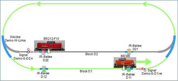
Here again is the schematic layout of the setup:
In the direction of travel of the locomotives, 2 IR-balises are installed in front of each signal. For example, suppose that the shunting locomotive BR365 is traveling towards the signal “Demo-S-D1-re” and the signal is set to “Stop”. The sequence is as follows:
- Travels through “Demo-W-Links”.
- Travels over IR-balise D12.
- The information sent by D12 has the following content: “This is IR-balise D12, the distance to the upcoming signal is 80 cm, the signal is set to ‘Stop’. “.
- The locomotive slowly reduces its speed so that it would come to a stop in 80 cm.
- Since the distance between D11 and D12 is less than 80 cm, D11 is crossed at a significantly reduced speed.
- Travels over IR-balise D11.
- The information sent by D11 has the following content: “This is IR-balise D11, the distance to the upcoming signal is 0 cm, the signal is set to ‘Stop’ “.
- The locomotive immediately reduces its speed and comes to a stop.
Implementation
The following describes the configuration of the module in “Demo-W-rechts” for the IR-balises D11 and D12.
When connecting the IR-balises, the CTC-App has already internally set up some configurations.
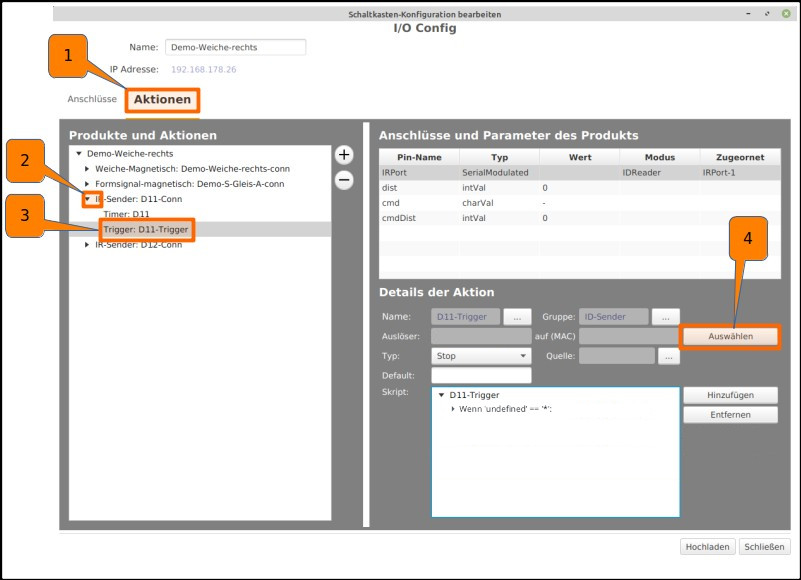
Clicking on “Settings” and “Configurator” opens the configurator. Clicking on the pencil icon in the SwitchBox row with the ID “Demo-W-rechts” opens the window “Edit Switch Box Configuration”.
- Clicking on the “Actions” tab opens the corresponding window.
- Clicking on the TRIANGLE NEXT TO “IR-Balise: D11-Conn” opens further options.
- Clicking on the “Trigger: D11-Trigger” field opens further options under “Action Details”.
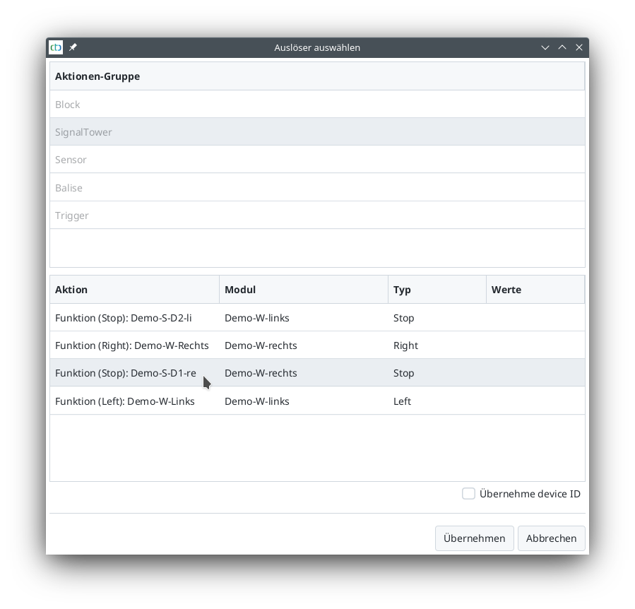
- Clicking on the “Select” field opens the window “Choose Trigger”.
Continuing with choosing the trigger:
- Under “Action Group”, select “SignalTower”,
- under “Action”, select “Demo-S-D1-re”,
- clicking on “Apply” closes the window.
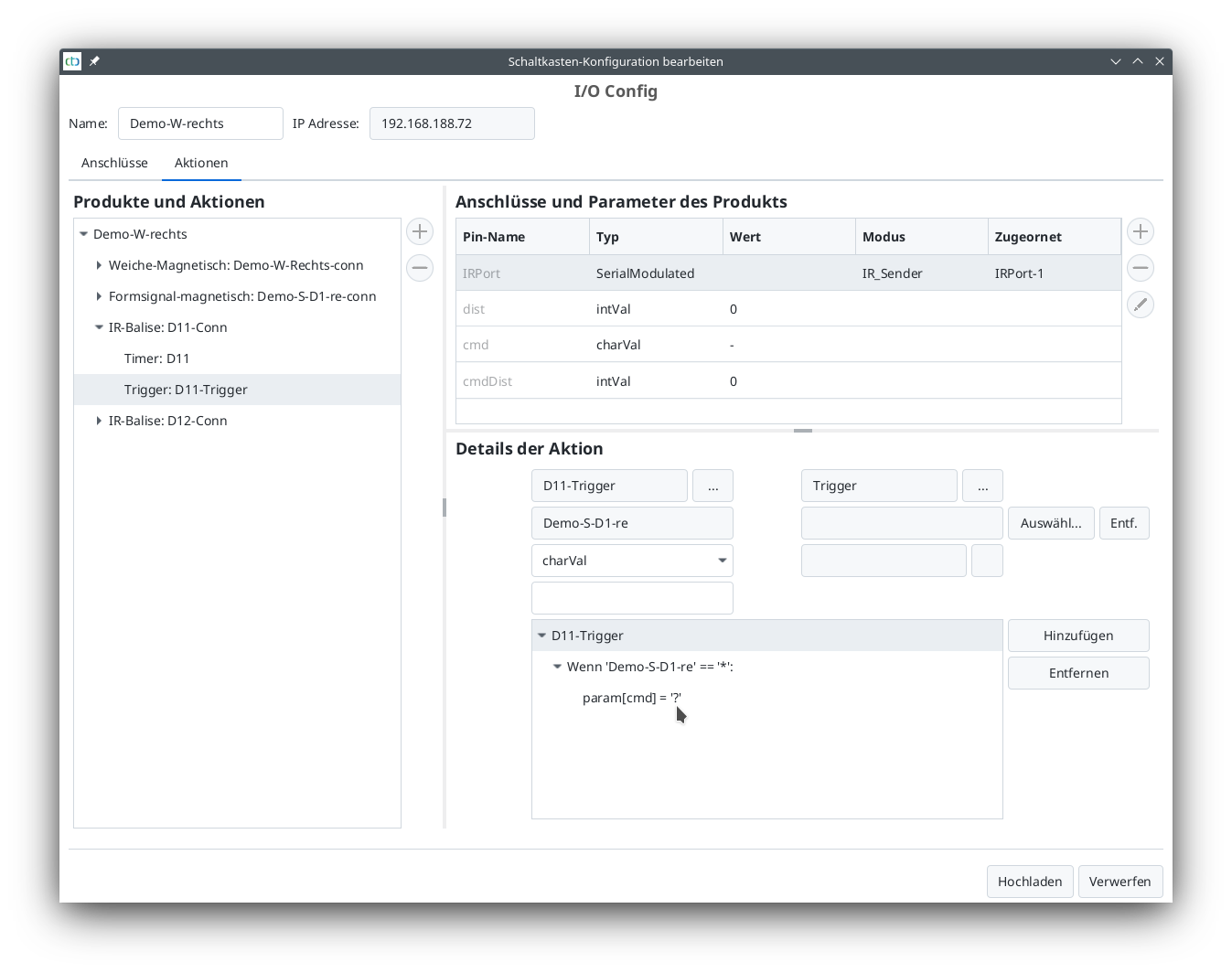
For the balise directly in front of the signal, the action details are already appropriately configured: In all cases (‘*’), the command remains unchanged to reflect the signal state (param[cmd]=’?’).
The IR-balise D12 is configured almost the same as D11. However, if the signal is red, the locomotive should not stop immediately but instead slow down to minimal speed over the distance to balise D11.
- Clicking on the TRIANGLE NEXT TO “IR-Balise: D12-Conn” opens further options.
- Clicking on the “Trigger: D12-Trigger” field opens further options under “Action Details”.
- Clicking on the “Select” field opens the window “Choose Trigger”.
- Under “Action Group”, select “SignalTower”,
- under “Action”, select “Demo-S-D1-re”,
- clicking on “Apply” closes the window.
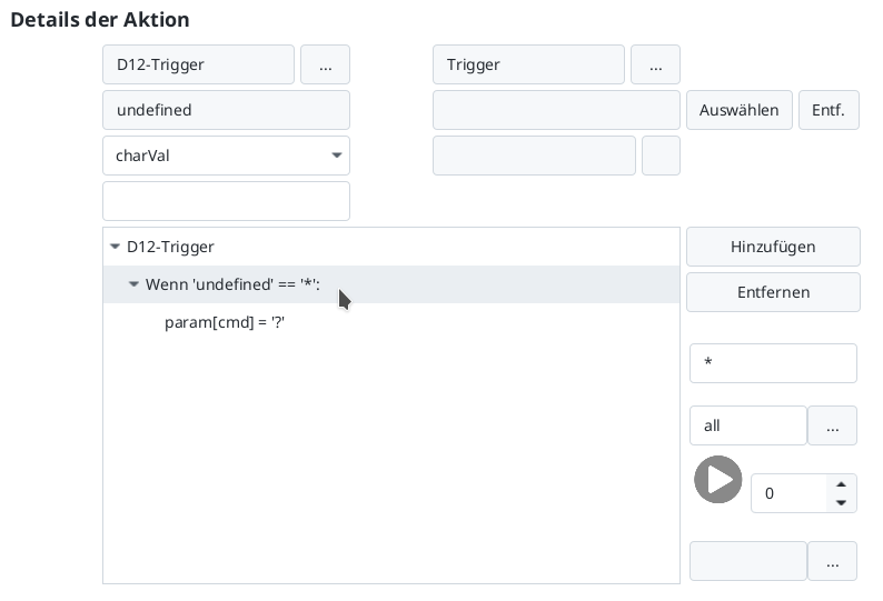
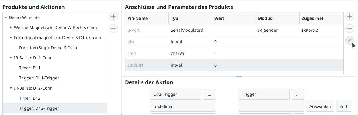
- In the “Action Details” section: Clicking on the TRIANGLE NEXT TO “D12-Trigger” opens further options.
- In the “Action Details” section: Clicking on the TRIANGLE NEXT TO “If ‘Demo-S-D1-re’ == ‘*’” opens further options.
- Clicking on the line “If ‘Demo-S-D1-re’ == ‘*’” displays the parameters of the If-command on the right.
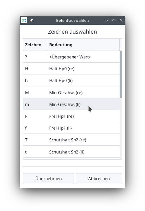
The special case “Signal red” needs to be treated first. Which letter is assigned to this state can be found in the manual in Chapter 4.5 “Config - Edit Script”.
Alternatively, one can simply view the config of the signal.
- Clicking on the TRIANGLE NEXT TO “Semaphore signal magnetic: Demo-S-D1-re-conn” opens further options.
- Clicking on “Function (Stop): Demo-S-D1-re” shows the action details.
- Clicking on the script “Switch to Hp0_Bar (‘h’)” shows the details of the state with the letter ‘h’. The symbol next to the script window speaks more than a thousand words.

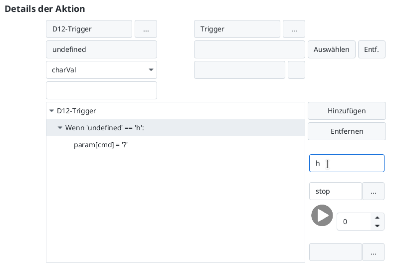
Back to the trigger, the state ‘h’ can now be entered in the If-command.
- Clicking on “Trigger: D12-Trigger” switches back to the trigger of balise D12.
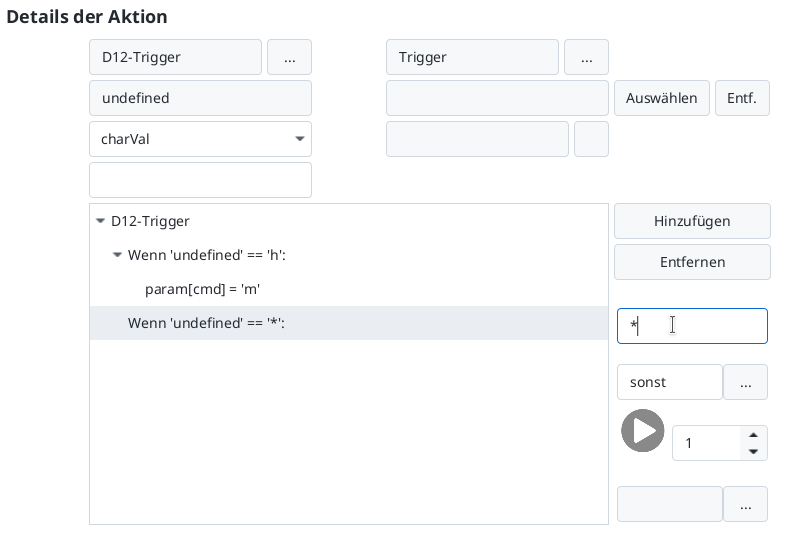
- Clicking on the line “If ‘Demo-S-D1-re’ == ‘*’” displays the parameters of the If-command on the right.
- Clicking in the field below the Remove button allows entering the letter ‘h’.
- In the field below, enter a name corresponding to the condition, e.g., “stop”.
Now specify what should happen at ‘h’:
- Clicking on “param[cmd] = ‘?’” displays the parameters of the “param” command on the right.
- Clicking the button next to ‘?’ opens the command selection.
In all other cases, the signal state is taken over again. A new If-command needs to be added for any state.
- Click on the top line in the script area (“D12-Trigger”).
- Then click on “Add”.
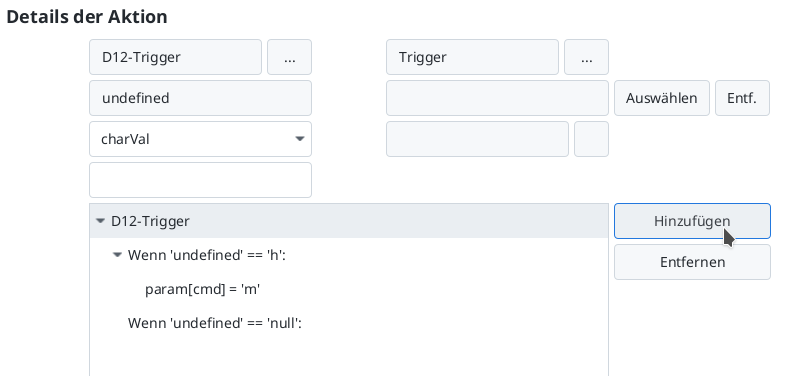
- Enter the asterisk (‘*’) as the condition for the If-command.
- In the field below, enter a name corresponding to the condition, e.g., “otherwise”.
- Change the script position below from 0 to 1.
Next, add the command for the new If-command.
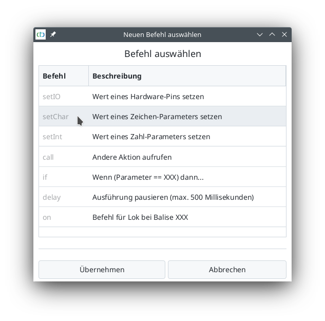
- Click on “Add” - the “Select New Command” window opens.
- Click on the “setChar” command.
- Then click on “Apply”.
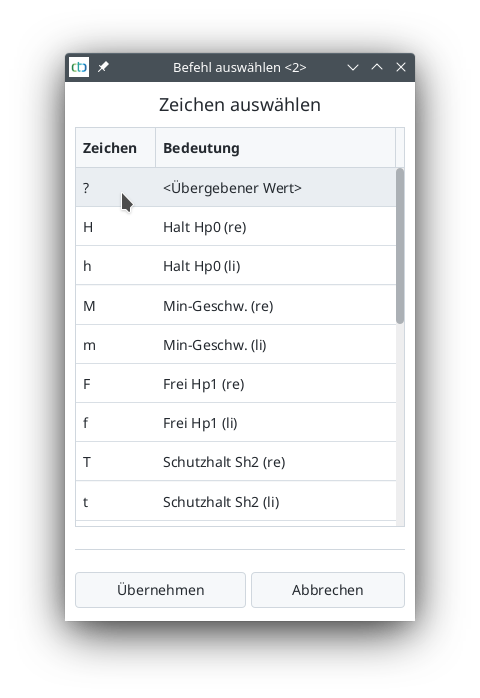
The line “param[?] = ‘?” is selected. Now specify that “cmd” should take over the state of the signal (‘?’):
- From the list under “Remove”, select the value “cmd”.
- Click the button on the left below the selection list - the “Select Command” window opens.
- Select the line ‘?’.
- Click on “Apply”.
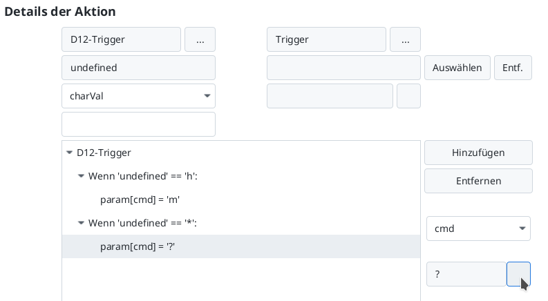
The script for the trigger of balise D12 is now complete:
What is still missing is the distance for braking. Since this is independent of the signal state, it is set fixed instead of changing it in the script.
- Click on the line “cmdDist” under “Connections and Parameters of the Product”.
- Click on the pencil icon to the right of the selected line.
Now balise D12 is also completely configured:
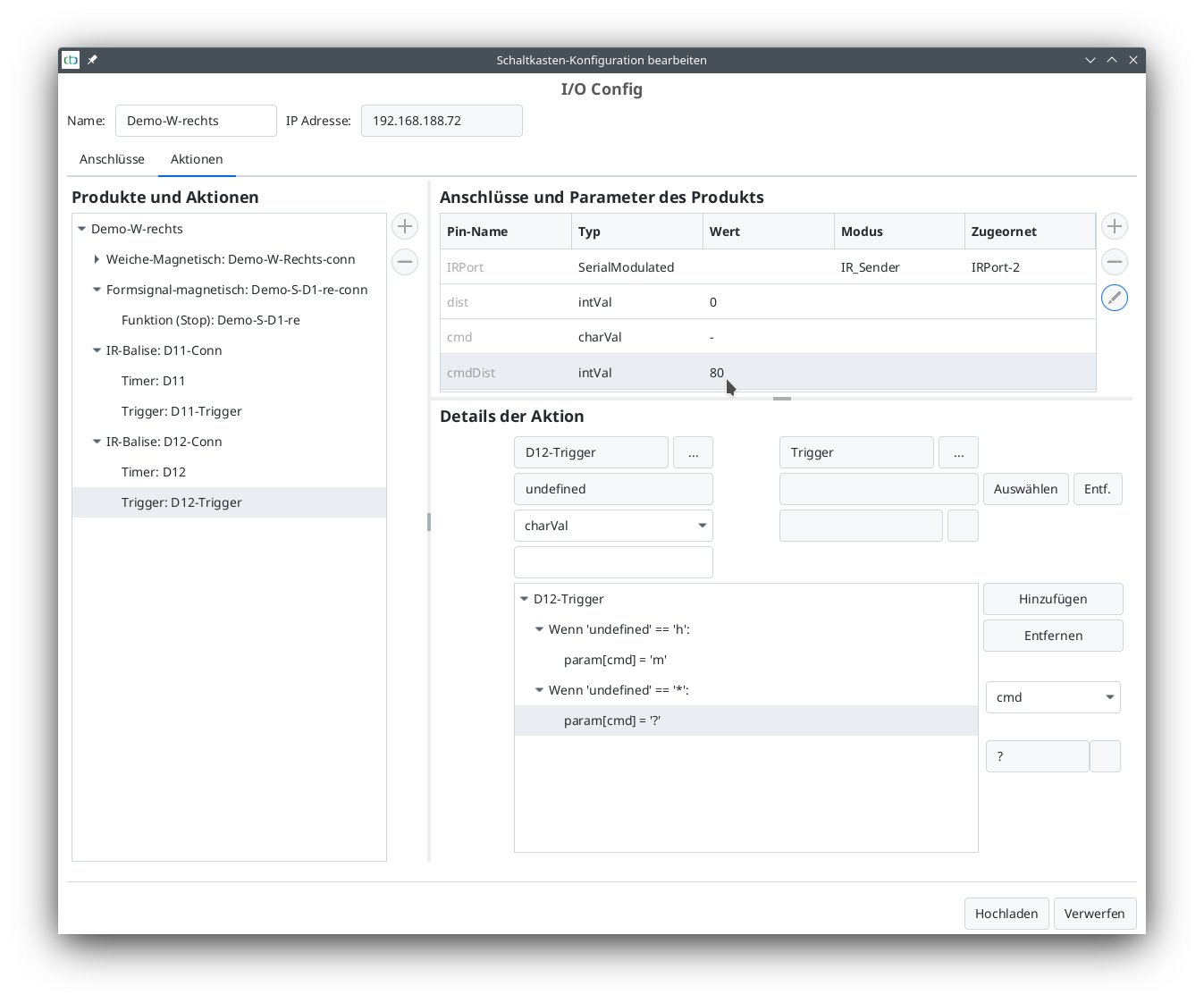
Clicking on “Upload” completes the changes to the triggers of both balises D11 and D12.
Configure Second Turnout Module
The second turnout module is configured the same way as the first turnout module. It has exactly the same connections: a turnout drive, a semaphore signal with magnetic drive, and two IR-balises. When selecting the products, note that this is a turnout that turns to the left.
The assigned names are:
- Module: Demo-W-Links
- Signal: Demo-S-D2-li
- IR-balises D22 (stop) and D21 (braking)
The configuration of the turnout modules is complete.
8. Train Operation with BR365 and E103
First, the BR365 is put into operation. In the “Locomotives” tab, click on the BR365, then select the “Control” tab. The default settings are shown here:
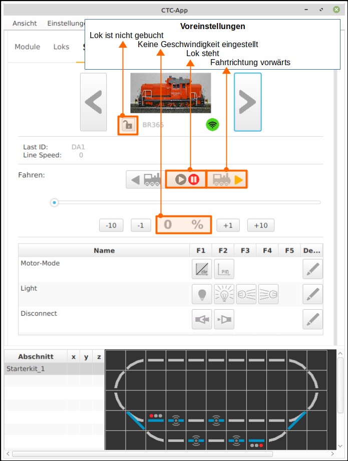
Driving with the BR365:
- The speed is preselected via the +/- buttons or with the slider in the “Control” tab.
- The two turnouts “Demo-W-Left” and “Demo-W-Right” are set for the BR365: A click on the turnout in the track diagram under the locomotive control changes the turnout position.
- The signal “Demo-S-D1-right” in front of the right turnout is set to “green”.
- After clicking the direction switch to the right, the BR365 locomotive starts moving counterclockwise, passes the signal “Demo-S-D1-right”, crosses the turnout “Demo-W-Right” and enters the loop.
- By clicking on the signal “Demo-S-D1-right”, the signal switches back to red. Now, the IR-balises D12 send “Brake to minimum speed in 80 cm” and D11 the message “Stop, signal is red”.
- BR365 receives this message via the IR receiver built into the locomotive (listed under the “Sensors” tab) when passing over the IR-balise.
- BR365 stops in front of the signal “Demo-S-D1-right”.
As shown in the following figure, a second locomotive can be displayed with “View” - “Show left panel”.
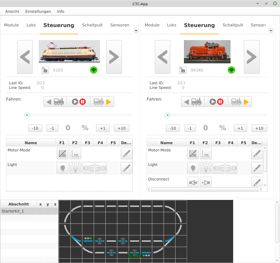
Now a round is driven with the E103:
- By clicking on “View” - “Show left panel”, another panel/window is opened. The window size is readjusted and the tab selected,
- Clicking on one of the two large arrows next to the image of the BR365 locomotive selects the next locomotive, in this case, the E103.
- The desired speed is preselected on the slider in the “Control” tab.
- The two turnouts “Demo-W-Left” and “Demo-W-Right” are set for the E103: A click on the turnout in the track diagram under the locomotive control changes the turnout position.
- The signal “Demo-S-D2-left” in front of the left turnout is set to “green”.
- After clicking the direction switch to the left, the E103 locomotive starts moving clockwise, passes the signal “Demo-S-D2-left”, crosses the turnout “Demo-W-Left” and enters the big loop.
- By clicking on the signal “Demo-S-D2-left”, the signal switches back to red. Now, the IR-balises D21 send “Brake to minimum speed in 80 cm” and D22 “Stop, signal is red”.
- E103 completes its lap and returns, first crossing D21 and arriving at D22. It receives the message “Signal is red” via the IR receiver built into the locomotive (listed under the “Sensors” tab) when passing over the IR-balise.
- E103 stops in front of the signal “Demo-S-D2-left”.
The goal is also for the locomotives to stop precisely in front of a signal set to “Stop”. For this, the sensors of the locomotives need to be calibrated.
9. Calibrate Sensor
Basic Idea
The desired outcome is that a locomotive stops precisely in front of a signal displaying “Stop.” In the starter set track layout, two IR-balises are embedded in the tracks before each signal. When a locomotive approaches the signal and passes over one of the IR-balises, it receives the following information:
- the ID of the IR-balises,
- whether the signal shows “Stop” or “Proceed” and
- the distance from the IR-balise to the signal.
This last piece of information allows the locomotive module to stop precisely in front of a signal set to “Stop.” The prerequisite for this is that the motor can be controlled precisely enough. To obtain the necessary control parameters for the motor, the sensor for motor control needs to be calibrated. The CTC app supports this process, which is referred to as “Calibrate Sensor.”
The following sections describe the individual steps. It is imperative to follow the procedure as outlined.
Requirements
To calibrate the sensor of a locomotive, a measurement track is needed. For this purpose, a measurement track is defined:
- A defined start: “measurement starts here”,
- a defined end: “now the end of the measurement track is reached” and
- the distance between the start and the end.
The necessary definitions are stored in the configuration of the CTC module, which controls the IR-balise and where the data of the model railway is stored. Each IR-balise is used as the start and end of the measurement track. The distance of the IR-balise comes from the model railway. If the locomotive travels this measurement track several times at different speeds, the control parameters for the locomotive’s motor can be calculated.
Note:
- Convention: The designation of the IR-balises has a running index in a clockwise direction.
- Convention: The track layout is traversed in a clockwise direction for measurement.
A prerequisite for calibrating the locomotive’s motor control sensor is that the most current firmware is loaded into the locomotive module. To ensure this:
- Open the configuration of the respective locomotive module,
- click on “Load Firmware,” which opens the selection window,
- select and confirm the firmware with a click on “Open,”
- the selected firmware is then transferred to the locomotive module.
Define Measurement Track
From the image of the track layout:
- the measurement starts at D21,
- the measurement ends at D22 and
- the length of the measurement track is the distance traveled from D21 to D22.
The start and end of the measurement are defined in the model railway. The length of the measurement track is stored in the configuration of the second IR-balise.
Start and End of the Measurement Track
The start and end of the measurement track are defined in the model railway. This is stored in the “Demo-turnout-right” module:
- Click on the “Modules” tab in the CTC app.
- Click on “Edit” for the “Demo-turnout-right” module to open the “Edit Control Box” window.
- In the “Edit Control Box” window - Click on “Change Model Railway.”
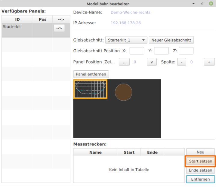
- The “Edit Model Railway” window opens - Click “New” under “Measurement Tracks.”
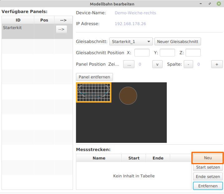
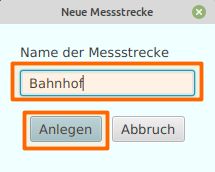
- Enter the name of the measurement track, in this case “Station,” and confirm by clicking “Create.”
- Back in the “Edit Model Railway” window, click “Set Start.”
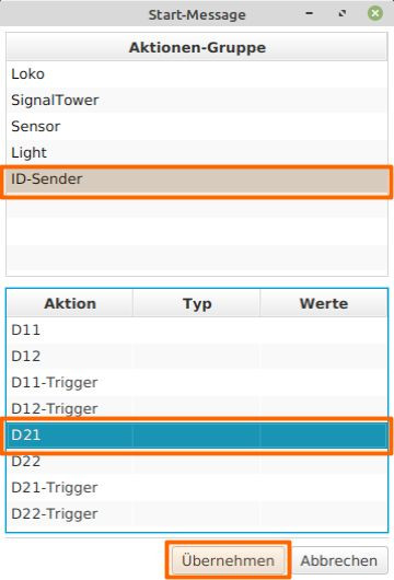
- The “Start Message” window opens. Select “ID Sender,” choose “D21” under “Action,” and click “Apply.”
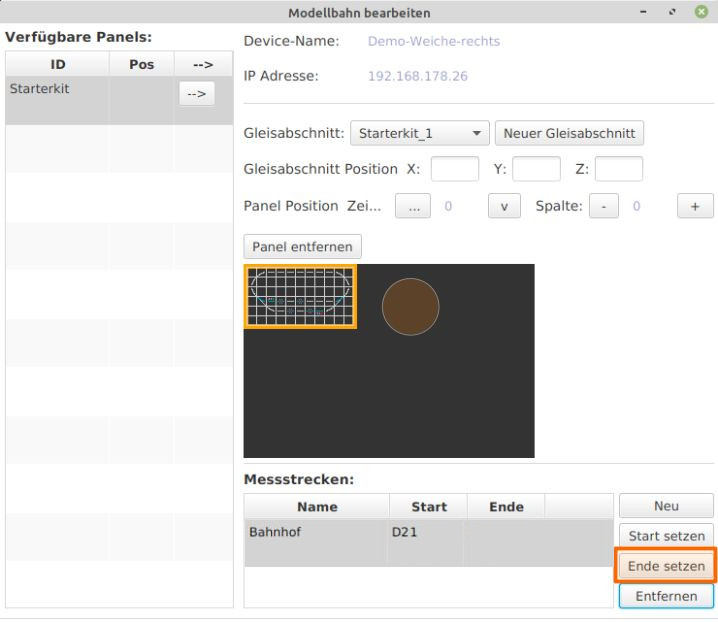
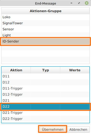
- Back in the “Edit Model Railway” window, click “Set End.”
- The “End Message” window opens. Select “ID Sender,” choose “D22” under “Action,” and click “Apply.”
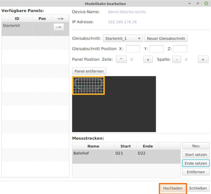
Now the start and end of the measurement track are defined in the model railway. In the current version of the app, only one measurement track should and can be defined; multiple measurement tracks are not possible. Back in the “Edit Model Railway” window - Click “Upload” and then “Close.”
Length of the Measurement Track
The following information needs to be conveyed: “When the locomotive passes over D21 and then over D22, it has traveled the distance from D21 to D22, which is XXX centimeters. In other words: “D22 is ‘xxx’ centimeters from D21.” The length of the measurement track is defined in the configuration of the respective IR-balise. In the starter set, IR-balises D21 (start) and D22 (end) are connected to “Demo-turnout-left.” This length information needs to be stored in the “Demo-turnout-left” module:
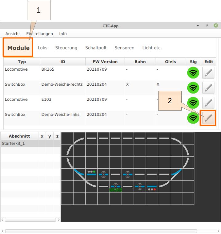
- Click on the “Modules” tab in the CTC app.
- Select “Edit” for the “Demo-turnout-left” module to open the “Edit Control Box Configuration” window for the Demo-turnout-left.
Selecting “Change Config” opens the “Edit Control Box Configuration” window.
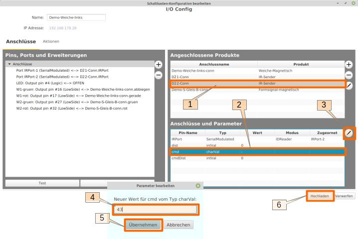
- In the “Connected Products” section, select “D22-Conn.”
- In the “Connections and Parameters” section, select the “dist” row.
- Click the edit pencil icon.
- Now enter the correct distance (in cm) from D21 to D22. In this setup, the distance between the two IR-balises is assumed to be 43 cm.
- Click “Apply” to complete the input and return to the “Edit Control Box Configuration” window.
- Click “Upload.”
Run Sensor Calibration
With this preparation, the sensor calibration of a locomotive can be carried out. The CTC app performs a series of measurements, with the locomotive traversing the measurement track at different speeds. The starting speed must be manually set by the user. The actual measurement cycle is carried out automatically by the CTC app, requiring no further intervention. The measurement track is traversed multiple times, with the speed increasing after every three rounds. The progress of the measurements can be tracked in the recorded measurement data graph.
In the main window of the CTC app, prepare the track for the locomotive:
- Set “Demo-turnout-left” to “Turn.”
- Set the “Demo-S-Track-B” signal in the station track to “Proceed.”
- Set “Demo-turnout-right” to “Turn.”
- Select the E103 locomotive and click “Edit” in the row.
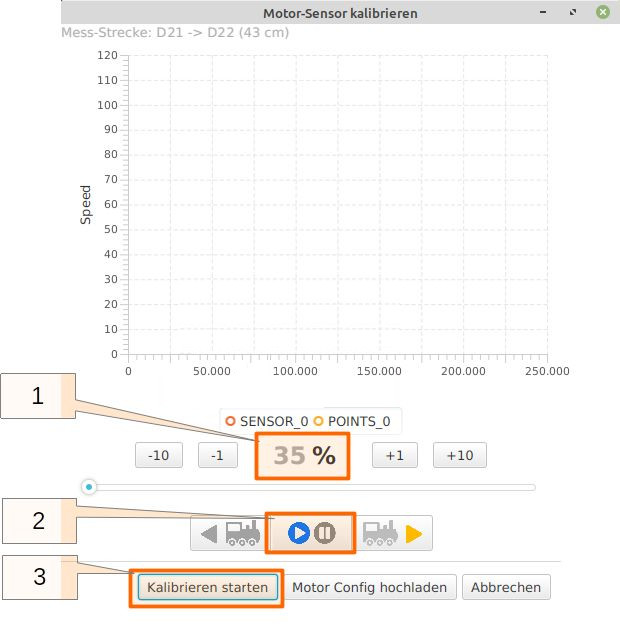
The configuration window for the locomotive opens, where you click “Calibrate Sensor.”
- The CTC app measurement cycle should start at the lowest possible speed for the locomotive. This must be set by the user. Typically, this value should be between 10 and 20 percent. For the locomotive used here, an exceptionally higher value of 35% must be set.
- By clicking “Start/Stop,” the locomotive sets off. The locomotive should run for some time, giving the opportunity to check the set minimum speed and adjust it if necessary.
- Click “Start Calibration” to start the measurement cycle, which runs autonomously.
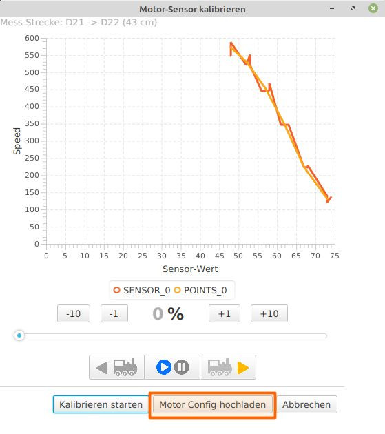
Once the locomotive has traversed the measurement track three times, the app automatically increases the speed by 10% increments. The track is then traversed three more times. This continues until the speed exceeds the 80% mark. In the “Calibrate Motor Sensor” window, the progress of data collection and analysis can be monitored.
When the measurement cycle is complete, the locomotive stops, and by clicking “Upload Motor Config,” the calibration values calculated by the app are transferred to the locomotive module, making them available for operation.
10. Automating Train Operation
Automating Train Operation
In progress, coming soon
10.1. Automate Train Operation with One Locomotive
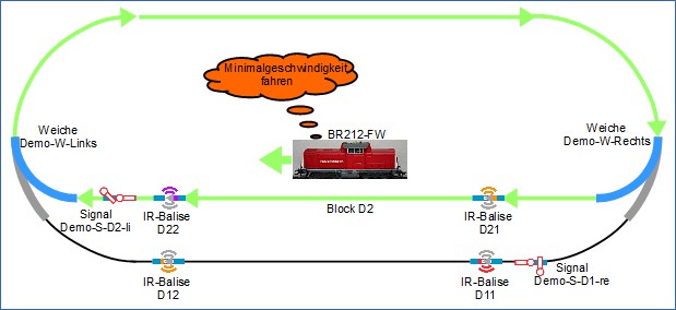
The scenario used here for automated train operation is as follows:
- The train with the locomotive BR212-FW enters the station,
- slows down and
- comes to a stop.
- The train stays at the station for a certain period.
- After the waiting period, the train continues, makes a clockwise round, and re-enters the station.
This operation repeats.
The following prerequisites must be met for the automated operation with one locomotive (in this example, BR212-FW) in this scenario. It is assumed that:
- The track plan is completed, the balises are connected to the modules in the turnouts.
- The waiting time for BR212-FW at the station should be 5 seconds.
- The turnouts are set in such a way that BR212-FW can make a round and re-enter the station.
- The signals Demo-S-D2-li and Demo-S-D1-re are not used; they are set to “Go”.
- BR212-FW is used for the automated operation, BR365 does not participate.
- The distance from balise D21 to balise D22 is 43 cm in the setup made here. For the command, which will later be sent from D21 to BR212-FW, a somewhat shorter distance (35 cm) is set, so the locomotive has safely reached its minimum speed when it arrives at balise D22.
Before proceeding, a brief explanation of the terms locomotive Halt, locomotive Stop, and locomotive Return is useful. These terms, in reference to commands from the balise, are used as follows:
- Halt denotes an unconditional and unlimited stop of the locomotive. As long as a locomotive receives Halt from a balise, it does not start moving.
- Stop means an unconditional but time-limited communicated in the command stop of the locomotive. After the waiting time communicated in the Stop command, the locomotive continues in the same direction.
- Return denotes an unconditional but time-limited communicated in the command stop of the locomotive. After the waiting time communicated in the Stop command, the locomotive continues in the opposite direction. This corresponds to shuttle train operation.
The description of commands that can be sent from a balise to the locomotive can be found in the user manual of the CTC-App in the chapter Config - Edit Script (section “Commands for locomotives / signals”). These commands will be used later in the configuration.
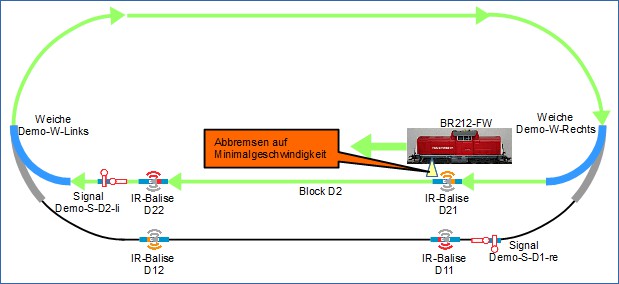
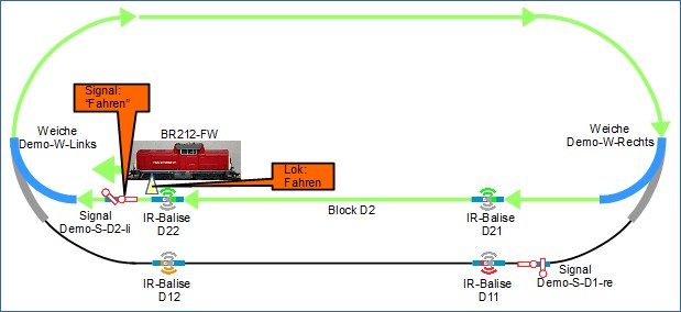
The detailed sequence of the scenario is described below. BR212-FW enters the station track:
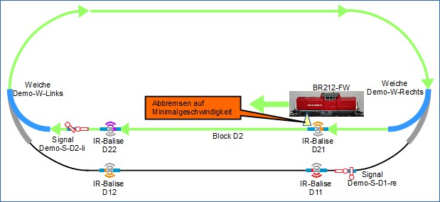
Upon entering the station track, BR212-FW passes over balise D21 and receives the following information:
- Position-ID D21: “I am D21”
- Distance to the previous balise in the same block (as there is no previous balise in the block, this value is 0).
- Command: “Brake to minimum speed in 35 cm”
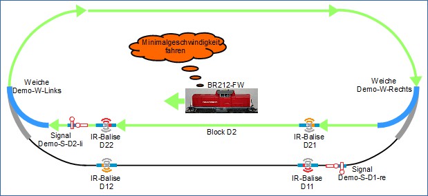
The locomotive BR212-FW slows down and continues at minimum speed …
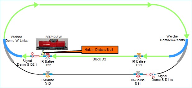
… until it passes balise D22:
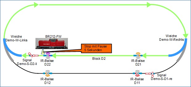
From balise D22, BR212-FW receives the following information:
- Position-ID D22: “I am D22”
- Distance to the previous balise in the same block is 35 cm.
- Command: “Stop immediately (at distance 0) for the time of 5 seconds”. (This implicitly means that the locomotive continues after the specified waiting time if it is in automation mode.)
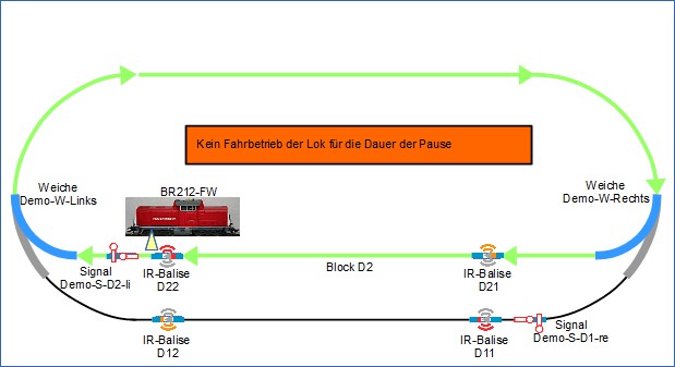
The locomotive waits for the waiting time transmitted in the command by the balise:
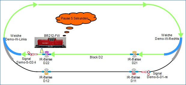
After the waiting time transmitted in the “Stop” command, BR212-FW continues:
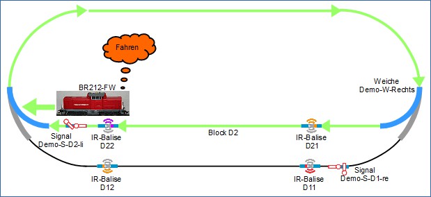
These necessary information and commands are configured.
Continue with Automate Train Operation with One Locomotive, Variant 2.
or
with Automate Train Operation with Two Locomotives.
10.2. Automating Train Operation with One Locomotive, Second Version
The scenario described now for automated train operation appears at first glance very similar to the scenario Automating Train Operation with One Locomotive, but it brings a bit more dynamics into play:
- The Signal Demo-S-D2-li is used,
- the commands sent by the balises D21 and D22 are not always the same but depend on the signal state Demo-S-D2-li (“Stop” or “Go”), and
- timers are used.
The scenario:
- BR212-FW drives one lap clockwise and enters the station,
- slows down, and
- comes to a stop.
- The train stays at the station for a certain time.
- After the stopping time, the signal Demo-S-D2-li switches to “Go”.
- BR212-FW starts moving.
- The signal Demo-S-D2-li switches back to “Stop” after a certain time.
This operation repeats itself.
The following prerequisites must be met for the automated operation and the following information is provided:
- The track plan is complete, the balises are connected to the modules in the turnouts.
- The stopping time of BR212-FW at the station should be 5 seconds.
- The turnouts are set so that BR212-FW can make a lap and re-enter the station.
- The signal Demo-S-D2-li is used.
- The signal Demo-S-D1-re is not used.
- The distance from balise D21 to balise D22 is 43 cm in the setup used here. For the command that will later be sent from D21 to BR212-FW, a slightly shorter distance (35 cm) is specified, so that the locomotive reliably reaches its minimum speed when it arrives at balise D22.
The description of the commands that can be sent from a balise to the locomotive can be found in the CTC-App instruction manual in the chapter Config - Edit Script (section “Commands for Locomotives / Signals”). These commands will be used later during configuration.
The more detailed sequence of the scenario is described below. BR212-FW enters the station track, with the signal Demo_S_D2_li showing “Stop”:
Upon entering the station track, BR212-FW crosses balise D21 and receives the following information:
- Position-ID D21: “I am D21”
- Distance to previous balise in the same block (since there is no previous balise in the block, this value is 0).
- Command: “Brake to minimum speed within 35 cm”
The locomotive BR212-FW slows down and continues at minimum speed …
… until it reaches balise D22:
From balise D22, BR212-FW receives the following information:
- Position-ID D22: “I am D22”
- Distance to previous balise in the same block is 35 cm.
- Command: “Stop at distance 0”.
The locomotive reports to the app that it has crossed balise D22. This report is used as a “trigger” to start the first timer. The first timer determines the dwell time of the locomotive at the station.
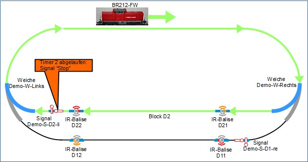
When the first timer expires, the signal changes to “Go”. This causes the message sent by balise D22 to no longer be “Stop at distance zero”, but instead “Go” is sent as the command. The signal Demo-S-D2-li switches to “Go”, and BR212-FW can start moving and leave the station:
The signal Demo-S-D2-li switches back to “Stop” after a short time (a second timer is configured for this), and BR212-FW makes another lap:
BR212-FW re-enters the station track:
The necessary information and commands for this scenario are now configured.
The corresponding instructions will follow shortly.
10.3. Automate Operations with Shuttle Train Service
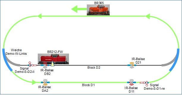
The locomotive BR212-FW is used for shuttle train service. The locomotive BR365 is not needed, it is removed from the layout.
The scenario used here for automated train operation is as follows:
- The train with the locomotive BR212-FW is at the station in block D2,
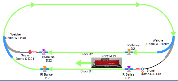
- BR212-FW starts moving counterclockwise,
- travels one round counterclockwise and enters the station block D1,
- slows down after balise D12 and
- comes to a stop at balise D11.
- The train stands for a specified rest period at the station in block D1 at balise D11.
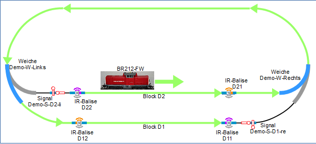
- After the rest period has elapsed, BR212-FW starts moving clockwise,
- travels one round clockwise and enters the station block D2,
- slows down after balise D21 and
- comes to a stop at balise D22.
- The train stands for a specified rest period (not identical to the rest time of block D1) at the station in block D2 at balise D22.
- After the rest period has elapsed, BR212-FW starts moving counterclockwise again.
This operation repeats itself.
The following prerequisites must be met for automated train operation with a locomotive in this scenario and the following information is available:
- The track plan is finished, and the balises are connected to the modules in the turnouts.
- The rest time of BR212-FW at the station in block D2 should be 5 seconds.
- The turnout Demo_W_Links is set so that BR212-FW makes one round counter-clockwise and enters the station Block D1.
- The turnout Demo_W_Rechts is set so that BR212-FW travels one round clockwise and enters the station Block D2.
- The signals Demo-S-D2-li and Demo-S-D1-re are not being used.
- BR212-FW is used for automated train operation, BR365 is not part of the operation.
- The distance from balise D21 to balise D22 is 43 cm with the setup performed here. For the command, which will later be sent from D21 to BR212-FW, a slightly shorter distance (35 cm) is set, ensuring that the locomotive has safely reached its minimum speed when it arrives at balise D22.
- The distance from balise D12 to balise D11 is 43 cm with the setup performed here. For the command, which will later be sent from D12 to BR212-FW, a slightly shorter distance (35 cm) is set, ensuring that the locomotive has safely reached its minimum speed when it arrives at balise D11.
Locomotive Halt, Locomotive Stop and Locomotive Reverse:
The terms Halt, Stop and Reverse are used in the following reference to the commands from the balise as follows:
- Halt designates an unconditional and unlimited in time stopping of the locomotive. As long as a locomotive receives Halt from a balise, it does not start.
- Stop denotes an unconditional but time-limited, communicated in the command stopping of the locomotive. After the waiting time contained in the command Stop has elapsed, the locomotive continues moving in the same direction.
- Reverse denotes an unconditional but time-limited, communicated in the command stopping of the locomotive.
After the waiting time contained in the command Stop has elapsed, the locomotive continues moving in the opposite direction. This corresponds to the shuttle service operation.
The description of the commands, which can be sent from a balise to the locomotive, can be found in the CTC-App operating instructions in the chapter Config - Edit Script (section “Commands for locomotives / signals”). These commands will be used for configuration later on.
Further description follows shortly.
10.4. Automating Train Operations with Two Locomotives
In the Automating Train Operations with One Locomotive
a static configuration was used.
In the scenario described now, this is different. This results in changes to the configurations.
The automated train operation is as follows:
- The train with locomotive BR212-FW is at the station in block D2.
- Signal Demo-S-D2-li switches to “Go”.
- BR212-FW starts moving, beginning to travel clockwise.
- Signal Demo-S-D2-li switches to “Stop”.
- BR212-FW completes one round clockwise and enters the station block D2,
- slows down, and
- comes to a halt.
- The turnouts switch so that BR365 can make a round.
- Signal Demo-S-D2-li switches to “Go”.
- BR365 starts moving, beginning to travel counter-clockwise.
- Signal Demo-S-D1-re switches to “Stop”.
- BR365 completes one round counter-clockwise and enters the station block D1,
- slows down, and
- comes to a halt.
- The turnouts switch so that BR212-FW can make a round clockwise.
- Signal Demo-S-D2-li switches to “Go”.
This train operation repeats.
For locomotive BR212-FW, the scenario is very similar to Automating Train Operations with One Locomotive, Variant 2.
The locomotive BR212-FW stops at the station track, signal Demo-S-D2-li switches to “Go”, BR212-FW starts moving, beginning to travel clockwise, signal Demo-S-D2-li switches to “Stop”, BR212-FW completes one round clockwise and enters the station, slows down and comes to a halt:
Now it’s BR365’s turn: The turnouts are switched so that BR365 can make a round counter-clockwise:
BR365 starts moving, beginning to travel counter-clockwise, signal Demo-S-D2-li switches to “Stop”:
BR365 enters the station, slows down:
The locomotive BR365 comes to a halt at balise D11.
These necessary information and commands are configured.
Further description will follow shortly.