


This text describes the configuration of turnouts modules for the starter set. The following is assumed:
- the track installation is set up,
- the turnover modules are built into the turnouts and the coil drive of the turnouts is wired,
- the signals are wired to the turnout modules,
- the IR balises are wired to the turnout modules,
- the power supply is complete,
- the turnout modules have been reset,
- the turnout drives are wired, and
- the semaphores are wired.
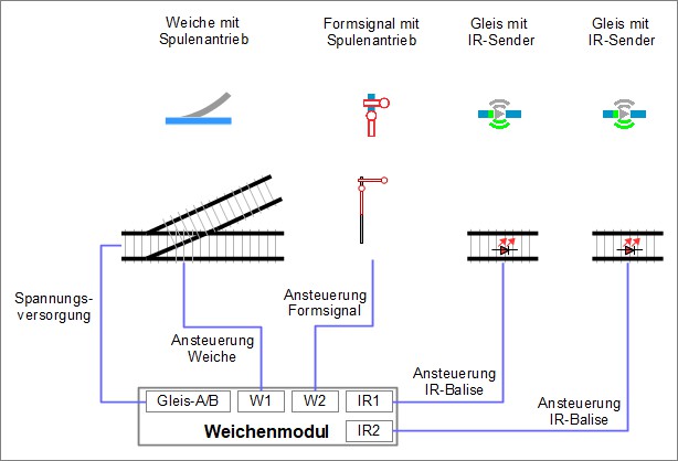
For your reference: The wiring for each of the turnout modules is carried out as follows:
Connecting the Turnout Product (magnetic) “Demo-W-right”
To connect the magnetic drive of the turnout to the turnout module (in terms of software connection), the configuration is called up:
- Click on the “Edit” icon in the line of “Demo-W-right” under the “Module” tab.
- The “Edit Junction Box” of the turnout module window will open.
- Click on the “Change Config” field.
- The “Edit Junction Box Configuration” window will open.
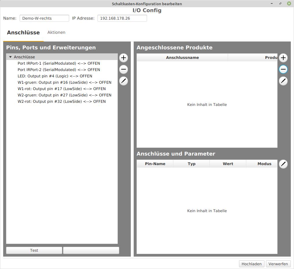
A turnout product is connected to the “W1-green” and “W1-red” terminals of the “Demo-W-right” module. When selecting the product to be connected next, it should be noted that it is a turnout that veers to the right in the direction of travel.
In the “Edit Junction Box Configuration” window, click on “+” in the “Connected Products” section to open the list of product catalogs and select a catalog.
- Select the catalog “universal-turnouts.xml” and
- Open it by clicking on “Apply” for further work.
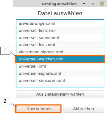
The “universal-turnouts” catalog is selected. From this catalog a name is assigned and a turnout is selected:
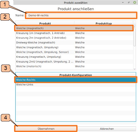
- Enter “Demo-W-right” as the product name in the “Select Product” window.
- The “Turnout (magnetic)” is selected as the product.
- “Turnout-Right” is selected for Product Configuration.
- Click on “Apply” to confirm the selection.
The CTC turnout module is already built into the turnout, and W1 is wired with the magnetic turnout drive. Now it’s time to make “the logical wiring” of the control. Knowing which pin / port of the turnout module switches the turnout to “turn” or “straight” is a prerequisite for this. The procedure is as follows:
- Select the “W1-green” output in the “Pins, Ports and Extensions” field.
- Click on the “Test” field. The turnout switches. Assumption: the turnout switches to “straight”
- Select the “W1-red” output in the “Pins, Ports and Extensions” field.
- Click on the “Test” field. The turnout switches. Assumption: the turnout switches to “turn”.
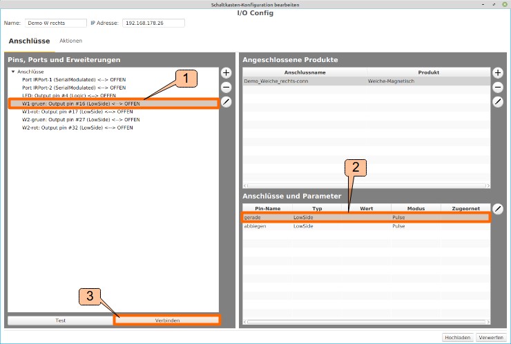
The pin names (“straight” and “turn”) mentioned in the “Connections” window of the product (“Demo-Turnout-right-conn”) are now connected with the connections mentioned in the “Pins, Ports and Extensions” window:
- Clicking on “W1-green: Output pin #16 (Low Side)” selects the pin of the turnout module.
- Click on “straight” under “Connections and Parameters” selects the pin name “straight” of the product.
- Click on “Connect” establishes the logical connection between “W1-green” and “straight”.
“W1-red: Output pin #17 (Low Side)” is also connected to “turn”.
- Click on “W1-red: Output pin #17 (Low Side)” selects the pin of the turnout module.
- Click on “turn” under “Connections and Parameters” selects the pin name “turn” of the product.
- Click on “Connect” establishes the logical connection between “W1-red” and “turn”.
The result of the connection work of the turnout module to the magnetic turnout drive looks like this in the CTC app:
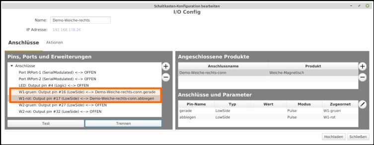
In the “Edit Junction Box Configuration” window, the action is completed by saving the configuration in the turnout module “Demo-Turnout-right” by clicking on “Upload”.
Connect the Product Turnout (magnetic) “Demo-Turnout-left”
For the second turnout, proceed similarly as described above. The configuration is called up with “Edit” from “Demo-Turnout-left”.
- Unlike “Demo-Turnout-right”, for “Demo-Turnout-left” in the “Connect Product” step, the product configuration “Turnout-left” should be selected.
The switching connections are tested and established as described above. In the “Switchbox Configuration Edit” window, the action is completed by clicking on “Upload” to save the configuration in the turnout module “Demo-Turnout-left”.