


Resetting the Configuration of CTC Turnout Modules
To be independent from any default settings and previous configurations, the CTC turnout modules are reset to their original state. This also applies to CTC Multi-IO modules, although these are not used in the starter set here.
Note: Whenever you are not 100% sure about how a module is configured, you should reset it before connecting anything to this module! Newly delivered modules from CTC are always in a reset state, i.e. with these, you don’t need to do anything.
The resetting of the CTC modules should have already been done, here is the corresponding chapter once more:
Installation of the Turnout Modules and Locomotive Modules.
First Steps to Configuring the CTC Turnout Modules
This text describes the first steps in configuring the turnout modules for the starter set “Locomotive and Turnout”. It is assumed:
- the track system is set up,
- the turnout modules are built into the turnouts and the magnetic drives are connected,
- the signals are wired to the turnout modules (but will only be configured later),
- the IR balises are wired to the turnout modules (but will only be configured later) and
- the power supply is complete.
The wiring of the signals and the IR balises for each of the turnout modules is carried out as follows:
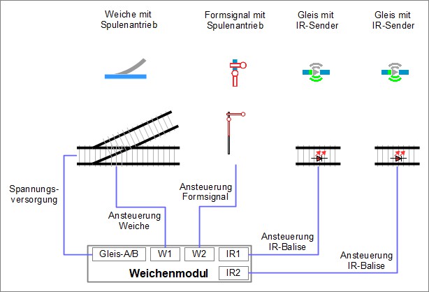
The wiring has been carried out, now it is time to inform the respective CTC turnout module, which “products” (turnout drive, semaphore signal and IR balises) are connected to which port of the module and how they are driven. When we talk about “connections” in the following, we do NOT mean electrical cables, but connections at software level.
The following steps are described and carried out in detail:
- “Products” are taken from the product catalogue. For each turnout module, the product catalogue includes
- one turnout,
- one semaphore signal and
- two IR balises.
- These products have “connections” that require a certain drive, this information is already included in the
product catalogue and is used by the CTC app to check for the correct connection:
- The magnetic drive of the turnout and the magnetic drive of the semaphore signal require a short pulse.
- The IR balises are driven with a pulse width modulated signal.
- The connections of the products are linked to the pins of the turnout module. The configuration of the turnout module is implicitly set according to the necessities for the drive of the respective product.
First Steps of Configuration
In the next step, the electrical connections must be communicated to the turnout modules. Connected to each turnout module are:
- the magnetic drive of the turnout
- the magnetic drive for a wing or form signal
- two IR balises, one very close to the signal and the other further in front.
The configuration of the right turnout module is being carried out.
Click on “Settings” - “Configurator” in the CTC app to open the “List of all Modules” window.

In the table, under “Type”, there are two modules of the type “SwitchBox”. These are the two turnout modules, which need configuring. During the reset, new names were already assigned, and these can be found in the “ID” column.
Alternatively, you can reach the “Edit Switch Box” window directly from the CTC app under the “Modules” tab:
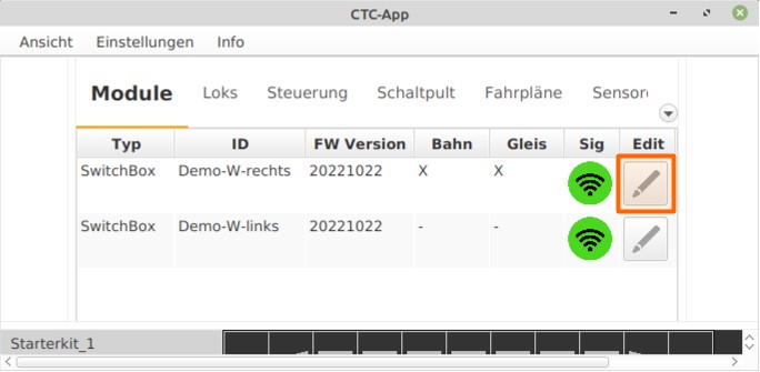
Clicking on “Edit” in the respective row of the “SwitchBox” list selects “Demo-W-right”. The “Edit Switch Box” window opens.
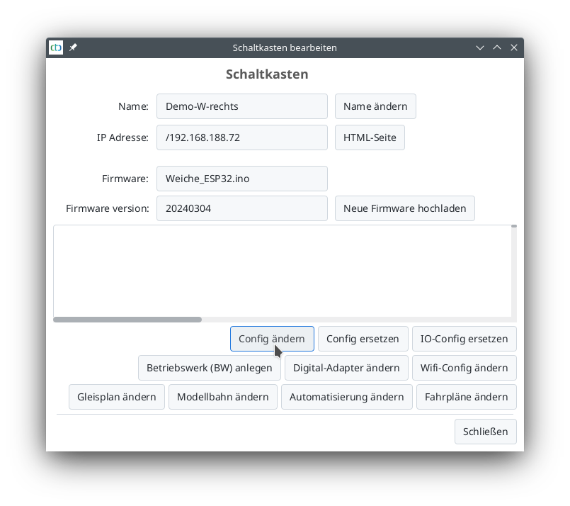
Clicking on “Change Config” opens the configuration window “Edit Switch Box Configuration”. The connection and function of the magnetic turnout drive are checked as follows:
- In the field “Pins, Ports, and Extensions” select the output “W1-green”.
- Click on the “Test” field. The turnout switches.
- In the field “Pins, Ports, and Extensions” select the output “W1-red”.
- Click on the “Test” field. The turnout switches.
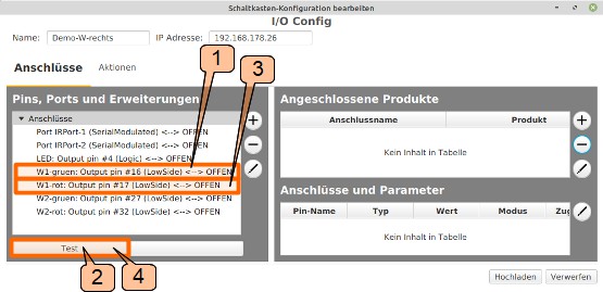
Now, the turnout has switched at least once, and it is known which connection switches the turnout to “straight” and which to “turn”. This information is needed for the correct connection of the turnout.