This chapter describes how
- the track layout is constructed
- the semaphore signals and the IR balises are connected to the turnout modules.
Starter Set Construction of the Track Layout
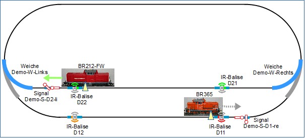
The layout plan consists of an oval with a stop, like a small station. The setup is constructed and the semaphore signals and IR balises are connected to the configured turnout modules. For the CTC starter set described here, two CTC locomotive modules and two CTC turnout modules are needed. Further chapters will describe how to build the track diagram “on the PC” using the CTC app. Subsequently, the setup will be “put into operation” and train operations will take place. It is assumed that one locomotive travels clockwise and another locomotive travels counterclockwise.
The layout is schematically represented in the following figure.

For constructing the track oval with the passing or station track, the following turnout and track material is used:
- Left curved turnout Article No. 24771 equipped with electric drive Article No. 74491
- Right curved turnout Article No. 24671 equipped with electric drive Article No. 74491
- 10x curved track R1, 30°
- 2x curved track R2, 30°
- 12x straight track 188.3 mm, of which 4 are retrofitted with CTC IR balises
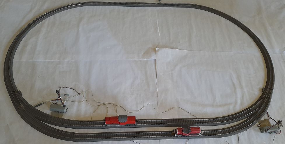
Top view of the layout, when it is assembled with the turnouts and tracks and the locomotives are placed on it:

The semaphore signals and IR balises will be connected next.
Connecting Semaphore Signals
The semaphore signals intended in this description have a magnet drive. The CTC turnout module used has a connection “W1”, this is used for the turnout drive and is already connected. The connection “W2” is used for the semaphore signal. The corresponding connector is designed as a three-pole linear socket connector. The operating voltage is applied to the central socket, the two outer connections are the switching functions. The magnet drive of the semaphore signal is to be connected accordingly.
| Label on Module | Output Function | Cable Color | Shrink Tube / Connector Color | Socket Position | Function on Semaphore Signal |
|---|---|---|---|---|---|
| W2-Red | Switch-1 | blue | red | Left | Magnet for switch state Hold |
| W2-VBB | Drive power supply | yellow | yellow | Center | Power supply |
| W2-Green | Switch-2 | blue | green | Right | Magnet for switch state Go |
Connecting IR Balises
Each of the CTC turnout modules controls two IR balises (infrared balises) in the starter set. The connection of IR balises to the turnout module is made according to the following table:
| Label on Module | Output Function | Shrink Tube Color | Socket Position | Function on IR Balise |
|---|---|---|---|---|
| IR1-GND | IR Balise 1 GND | green | Center-Left | IR Balise 1 Diode Cathode |
| IR1-VCC | IR Balise 1 VCC | red | Left | IR Balise 1 Diode Anode |
| IR2-VCC | IR Balise 2 VCC | red | Right | IR Balise 2 Diode Anode |
| IR2-GND | IR Balise 2 GND | green | Center-Right | IR Balise 2 Diode Cathode |
Further information on the setup and connection of IR balises to the turnout module can be found here:
The track layout is now constructed and the turnout modules can be configured.


