


This text describes the configuration of the turnout modules for the starter set. It is assumed that:
- the railway track has been constructed,
- the turnout drives are wired,
- the turnout modules are reset and the names have been assigned (Demo-turnout-left, Demo-turnout-right),
- the signals are wired to the turnout modules,
- the IR balises are wired to the turnout modules (the IR balises will not yet be needed for the time being) and
- the power supply is complete.
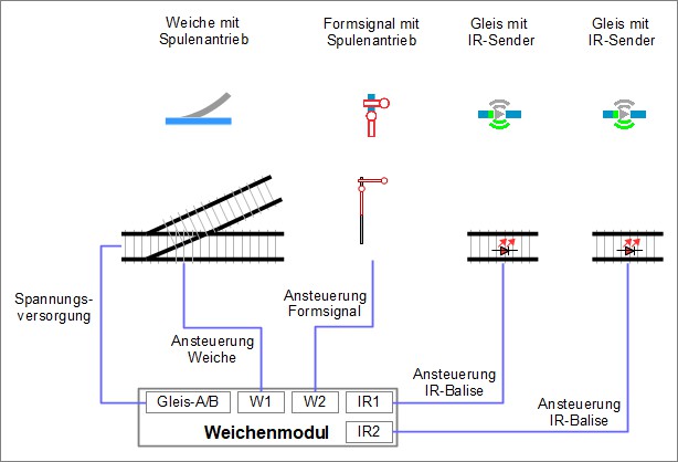
To recap: The wiring for each of the turnout modules is carried out as follows:
#
Connecting Product Semaphore Signal (magnetic) to Demo-Turnout-right
The magnetic drive for the semaphore signal is connected in a very similar way to the magnetic drive for the turnout.
To connect the magnetic drive of the semaphore signal to the turnout module (link them from a software perspective), the configuration is accessed as follows:
- In the “Modules” tab, click on the “Edit” icon in the row of “Demo-Turnout-right”.
- The “Edit Control Box” window of the Demo-Turnout-right will open.
- Click on the “Change Config” field.
- The “Edit Control Box Configuration” window opens.
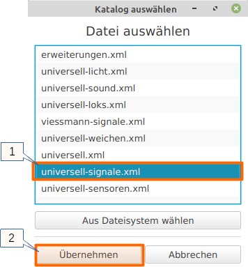
In the “Edit Control Box Configuration” window, click on “+” in the “Connected Products” area to open the list of product catalogs.
- Select the catalog “universal-signals.xml” and
- click on “Apply” to proceed with further tasks.
The “universal-signals” catalog is selected. From this catalog, a name is assigned and a signal is selected. The information “right” or “left” refers to the direction of travel (clockwise) that the signal should apply to (“right” means “clockwise”):
- Enter “Demo-S-Track-A” in the “Name” field
- “Semaphore Signal (magnetic)” is selected as Product
- “Semaphore Signal right” is chosen as the Product Configuration and
- by clicking on “Apply”, the semaphore signal is ready for connection.
.jpg)
After clicking “Apply”, you will return to the “Edit Control Box Configuration” window.
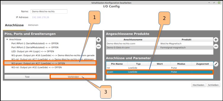
As with the connection of the turnout control, “w2-green: Output pin #27 (Low Side)” or “W2-red: Output pin #32 (Low Side)” is selected and its function is tested by clicking “Test”. Assumption: At “W2-green” the semaphore signal switches to “free ride” and at “W2-red” the signal switches to “halt”. The connection of the semaphore signal is carried out in a manner similar to the magnetic turnout drive:
- Select “W2-green: Output pin #27 (Low Side)” in the “Ports” section,
- choose “green” under “Connectors”, and
- click “Connect”.
Just as the “W2-green” pin was connected to the “green” connection, the “W2-red” pin is also connected to the “red” connection. The semaphore signal, like the turnout drive, is now completely connected:
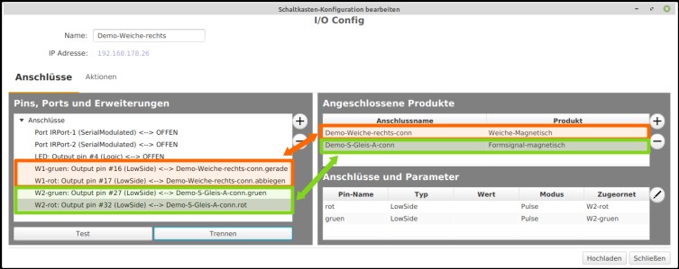
In the “Edit Control Box Configuration” window, the action is completed by uploading the configuration to the turnout module “Demo-Turnout-right” with a click on “Upload”.
Connecting the Semaphore Signal (magnetic) to the Demo Turnout-Left
For the semaphore signal, which is connected to the Demo Turnout-Left, proceed in a similar manner as described above. Use the “Edit” of “Demo Turnout-Left” to call up the configuration. In the further course, this signal is given the name “Demo-S-Track-B”. In the “Switch box configuration edit” window, the action is completed by clicking on “Upload” to save the configuration in the turnout module “Demo Turnout-Left”.
The turnout modules are configured, the turnouts and semaphore signal switch.