


Scripts exist in functions, triggers, and timers. They define a sequence of simple commands that are executed when the action reaches a specific state.
Scripts consist of the following simple commands:
pin[]: Set an output pin to a specific value.param[]: Set a parameter to a specific value.pause(): Wait for a specified number of milliseconds.call(): Call another action on the same CTC module, e.g., a timer.wenn (): Execute the commands under “wenn” only if a parameter has a specific value.
In the script for a driving order, there is an additional command:
on XXX: The locomotive should pass balise XXX and optionally execute a command—see Chapter 7.3 - Driving Orders
Note:
- The commands
callandifcreate nesting. If a script’s nesting exceeds 10 levels, it will terminate with an error starting from CTC-App 4.40 and firmware 20250627. - From CTC-App 4.40 onward, script execution and state changes are logged in the file “Action-Log.csv”. This file is located in the CTC-App’s data folder and is recreated (overwriting old content) each time the CTC-App starts. It can be conveniently viewed with LibreOffice Calc (Excel may work but is not guaranteed).
When an action’s state changes depends on the type of action:
- Functions and value controllers are changed by the user in the CTC-App by pressing a button or adjusting a slider.
- Timers are triggered automatically by the CTC module either once after a set time or at regular intervals.
- Sensors are triggered via switches. These can be pressed manually or activated by a passing locomotive or wagon.
- Triggers are activated as a result of another action. Triggers can be functions, value controllers, sensors, or IDs read by locomotives.
The top level of the script defines how the action should respond to specific values.
In the value configuration, the actions possible for a function are defined (they are part of the cfg.xml).
For example, for a locomotive’s light, the following four actions can be defined:
- off
- on
- front
- back
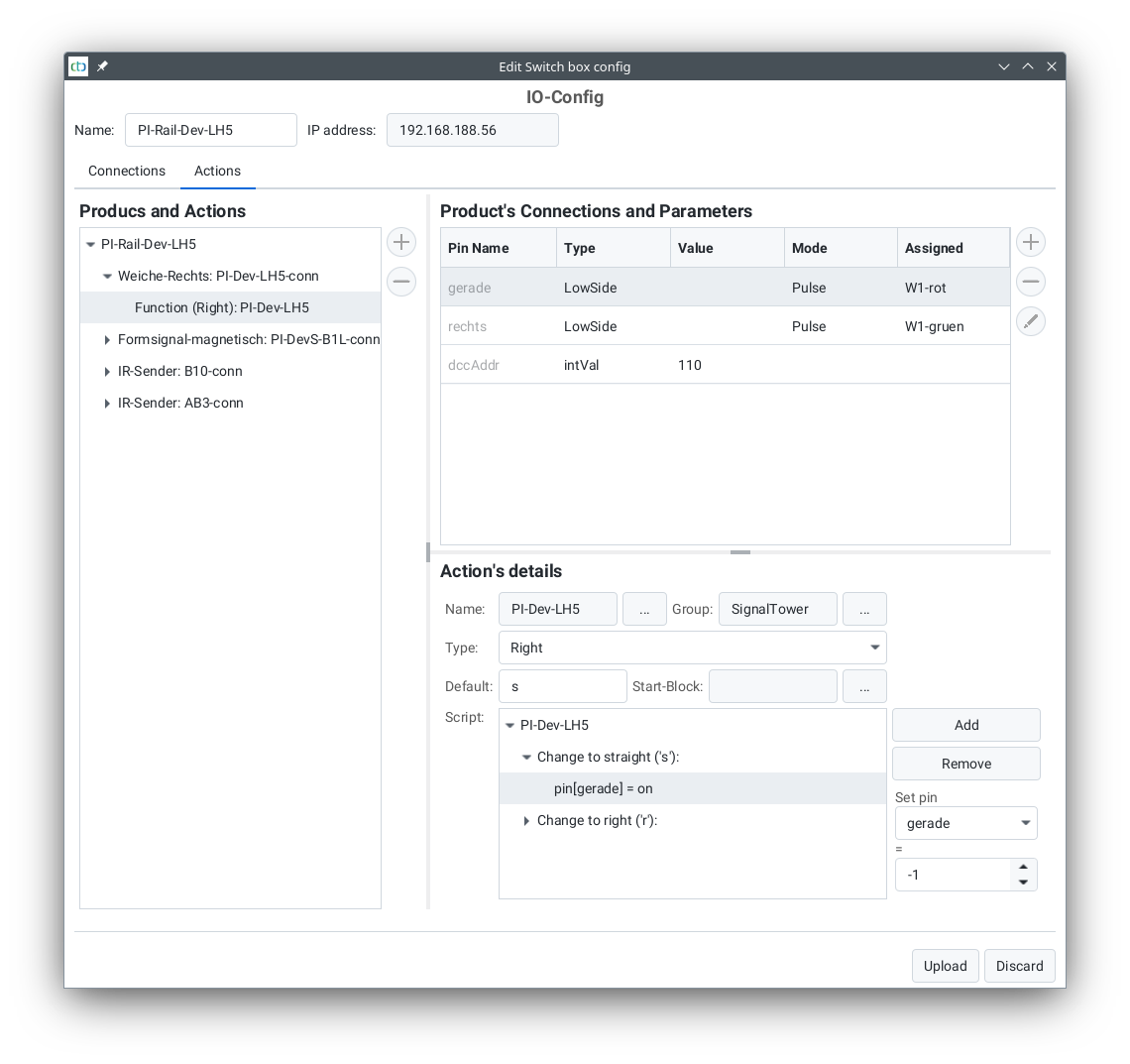
For each action, you can specify which of the outputs defined in the IO configuration should be switched. This is often just a single output, but it can also be a conditional sequence, as shown in the example dialog for the straight action of the turnout PI-Dev-LH5.
For turnouts, note that the icon displayed in the turnout list is determined by the action name. The position (0 to 2) indicates the column in the turnout view:
| Function | Action Name | Symbol | Icon | Recommended Position |
| Left turnout | left_left | l |  |
0 |
| left_straight | s |  |
1 | |
| Right turnout | right_straight | s |  |
1 |
| right_right | r |  |
2 | |
| Three-way turnout | three_left | l |  |
0 |
| three_straight | s |  |
1 | |
| three_right | r |  |
2 | |
| Crossing turnout | cross_notcross | x |  |
0 |
| cross_cross | n |  |
1 | |
| 4-way crossing turnout | cross_hor | h |  |
0 |
| cross_vert | v |  |
1 | |
| cross_left | l |  |
2 | |
| cross_right | r |  |
3 |
Commands for Locomotives / Signals
The following commands can be interpreted by locomotives when linked to a balise:
| Function | Symbol | Meaning | cmdDist | Description |
| Stop (Hp0 / red) | ‘H’, ‘h’ | Indicates an upcoming red signal. | Distance | The locomotive brakes and stops before this signal. If the signal turns green again, the locomotive resumes travel and accelerates to the maximum speed permitted by the signal. |
| Proceed (Hp1 / green) | ‘F’, ‘f’ | Indicates a green signal. | Distance | Any previous speed restriction is lifted. In manual control, nothing happens; otherwise, the locomotive accelerates to its maximum speed. |
| Slow Speed (Hp2 / green+yellow) | ‘W’, ‘w’ | Indicates slow-speed operation. | Distance | If the locomotive is too fast, it brakes to a reduced speed (e.g., to prevent derailment over a diverging turnout). |
| Speed Restriction | ‘L’, ‘l’ | Indicates a speed restriction. | Speed | If the locomotive is too fast, it brakes to this speed. The distance value is multiplied by 10 and interpreted as speed (e.g., “50” = 50 cm/s). |
| Minimum Speed | ‘M’, ‘m’ | Indicates an upcoming red signal with a second balise for the final stop. | Distance | The locomotive slows to a crawling speed. The second balise before the signal then sends a “Stop” command with a distance of 0 cm or an emergency stop. |
| Emergency Stop | ‘E’, ‘e’ | Emergency stop (e.g., just before track end or signal). | Distance | The locomotive stops abruptly. If the signal turns green again, it resumes travel and accelerates to the maximum speed permitted by the signal. |
| Stop | ‘S’, ‘s’ | Indicates an upcoming scheduled stop. | Pause (seconds) | In automatic mode, the locomotive stops, waits for the pause duration, and then continues. From CTC-App 4.08: In manual mode, behaves like a protective stop with distance 0. |
| Return Trip | ‘R’, ‘r’ | Indicates an upcoming stop at a timetable reversal point (e.g., shuttle train). | Pause (seconds) | In automatic mode, the locomotive stops, waits for the pause duration, and then continues in the opposite direction. From CTC-App 4.08: In manual mode, behaves like a protective stop with distance 0. |
| Protective Stop (Sh2) | ‘T’, ‘t’ | Indicates the end of track (e.g., buffer stop). | Distance | The locomotive brakes and stops before this marker. |
Almost every command is associated with a distance in cm, determining where the command takes effect. The locomotive calculates its braking distance accordingly—for example, a “Stop” command with a distance of “65” ensures the locomotive comes to a halt after 65 cm.
Note: A properly calibrated motor sensor is required for functional target braking (see Chapter “Calibrating the Motor Sensor”).
Commands can either be permanently assigned to a balise or dynamically modified using “triggers.” For example, a balise can be linked to a signal’s state (see Chapter “Config – Linking Actions”). For this reason, the same letters should be used for signal states as for the corresponding locomotive command.