


For precise target braking in front of a red signal or even for load regulation, the CTC locomotive module needs to know how fast the locomotive is actually moving. For this purpose, a sensor is installed in the motor driver of the locomotive, which provides a rough indication of the motor’s speed based on current flow. The calibration process determines a characteristic curve that maps the sensor values to speed.
For a calibration to be carried out, a measuring track consisting of two balises must be present. During the calibration, the locomotive autonomously drives over the balises in a circuit or shuttles back and forth.
Note: This process is detailed within the context of the Starter Set, see Starter Set Sensor Calibration
Define Measurement Track
The measurement track is defined in the “Edit Model Railway” dialog:
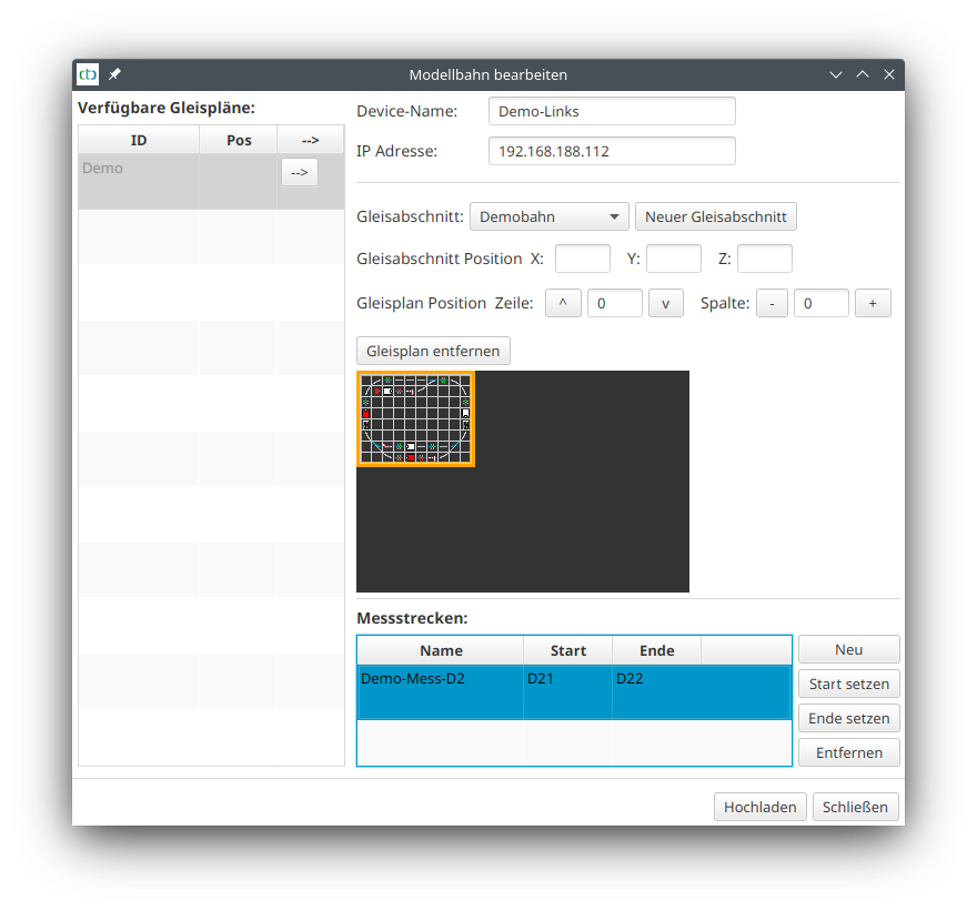
The two balises must belong to the same block (first two characters identical) and must come directly after each other. The “distance to predecessor” of the balise with the higher number then determines the length of the measurement track.
Calibrate Motor-Sensor
Open the dialogue “Calibrate Motor-Sensor” via the button “Calibrate Sensor” in the Locomotive Configuration of the respective locomotive.
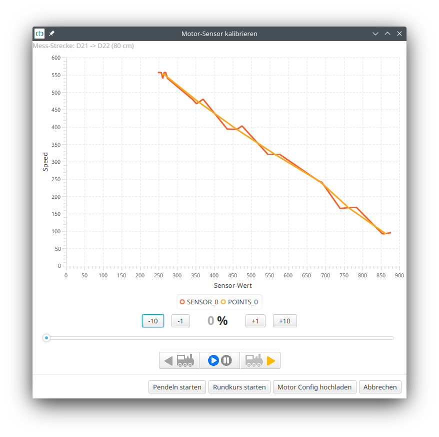
At the top, the measurement track is displayed. Check again if the balise designations and distance are correct.
Accelerate the locomotive to the minimum speed at which it still runs well. Then start the calibration process by clicking on “Start Pendulum” or “Start Circuit”.
Note: When pendulum swinging, the locomotive needs considerable space at both ends of the measuring track.
The locomotive drives the measuring track three times, then accelerates by 10% and drives the measuring track three times again. This repeats until the locomotive has exceeded 80%, then it stops.
The dialog then looks like this, for example, as in the picture above for the Piko BR 147. If you are satisfied with the result, click on “Upload Motor Config”.
Note: Those who want to know exactly will find the data transmitted during the measurement as “Motor-Setup.csv” in their user directory. This can be opened, for example, with Excel or LibreOffice and can be evaluated in detail there.