Basic Idea
The desired outcome is that a locomotive stops precisely in front of a signal displaying “Stop.” In the starter set track layout, two IR-balises are embedded in the tracks before each signal. When a locomotive approaches the signal and passes over one of the IR-balises, it receives the following information:
- the ID of the IR-balises,
- whether the signal shows “Stop” or “Proceed” and
- the distance from the IR-balise to the signal.
This last piece of information allows the locomotive module to stop precisely in front of a signal set to “Stop.” The prerequisite for this is that the motor can be controlled precisely enough. To obtain the necessary control parameters for the motor, the sensor for motor control needs to be calibrated. The CTC app supports this process, which is referred to as “Calibrate Sensor.”
The following sections describe the individual steps. It is imperative to follow the procedure as outlined.
Requirements
To calibrate the sensor of a locomotive, a measurement track is needed. For this purpose, a measurement track is defined:
- A defined start: “measurement starts here”,
- a defined end: “now the end of the measurement track is reached” and
- the distance between the start and the end.
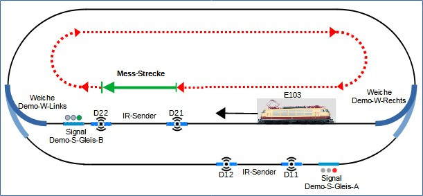
The necessary definitions are stored in the configuration of the CTC module, which controls the IR-balise and where the data of the model railway is stored. Each IR-balise is used as the start and end of the measurement track. The distance of the IR-balise comes from the model railway. If the locomotive travels this measurement track several times at different speeds, the control parameters for the locomotive’s motor can be calculated.
Note:
- Convention: The designation of the IR-balises has a running index in a clockwise direction.
- Convention: The track layout is traversed in a clockwise direction for measurement.
A prerequisite for calibrating the locomotive’s motor control sensor is that the most current firmware is loaded into the locomotive module. To ensure this:
- Open the configuration of the respective locomotive module,
- click on “Load Firmware,” which opens the selection window,
- select and confirm the firmware with a click on “Open,”
- the selected firmware is then transferred to the locomotive module.
Define Measurement Track
From the image of the track layout:
- the measurement starts at D21,
- the measurement ends at D22 and
- the length of the measurement track is the distance traveled from D21 to D22.
The start and end of the measurement are defined in the model railway. The length of the measurement track is stored in the configuration of the second IR-balise.
Start and End of the Measurement Track
The start and end of the measurement track are defined in the model railway. This is stored in the “Demo-turnout-right” module:
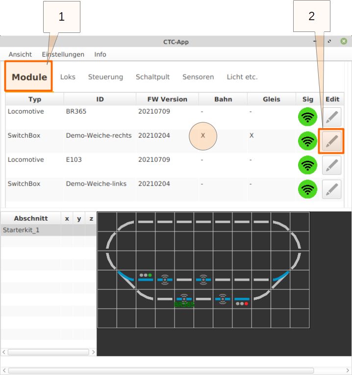
- Click on the “Modules” tab in the CTC app.
- Click on “Edit” for the “Demo-turnout-right” module to open the “Edit Control Box” window.
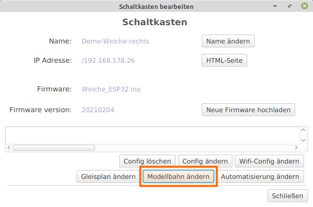
- In the “Edit Control Box” window - Click on “Change Model Railway.”
- The “Edit Model Railway” window opens - Click “New” under “Measurement Tracks.”
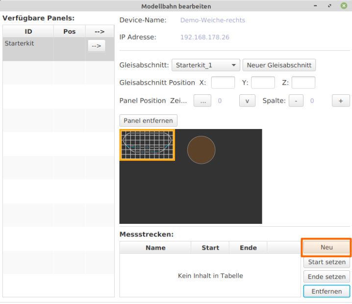
- Enter the name of the measurement track, in this case “Station,” and confirm by clicking “Create.”
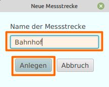
- Back in the “Edit Model Railway” window, click “Set Start.”
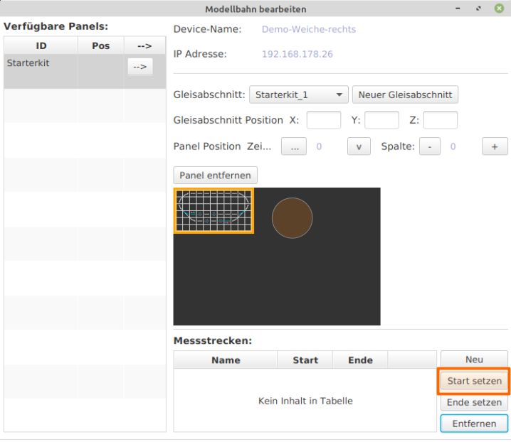
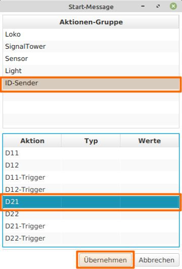
- The “Start Message” window opens. Select “ID Sender,” choose “D21” under “Action,” and click “Apply.”
- Back in the “Edit Model Railway” window, click “Set End.”
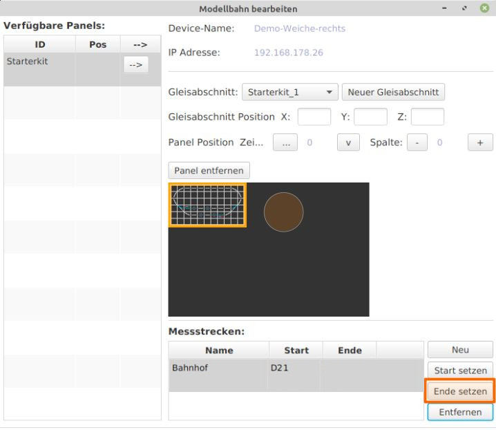
- The “End Message” window opens. Select “ID Sender,” choose “D22” under “Action,” and click “Apply.”
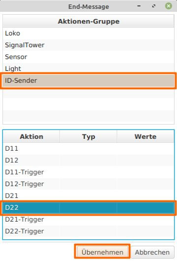
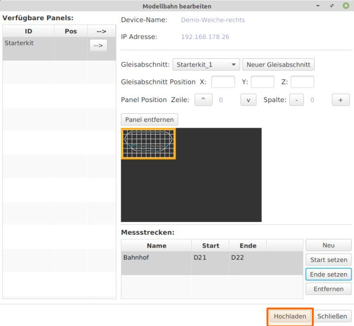
Now the start and end of the measurement track are defined in the model railway. In the current version of the app, only one measurement track should and can be defined; multiple measurement tracks are not possible. Back in the “Edit Model Railway” window - Click “Upload” and then “Close.”
Length of the Measurement Track
The following information needs to be conveyed: “When the locomotive passes over D21 and then over D22, it has traveled the distance from D21 to D22, which is XXX centimeters. In other words: “D22 is ‘xxx’ centimeters from D21.” The length of the measurement track is defined in the configuration of the respective IR-balise. In the starter set, IR-balises D21 (start) and D22 (end) are connected to “Demo-turnout-left.” This length information needs to be stored in the “Demo-turnout-left” module:
- Click on the “Modules” tab in the CTC app.
- Select “Edit” for the “Demo-turnout-left” module to open the “Edit Control Box Configuration” window for the Demo-turnout-left.
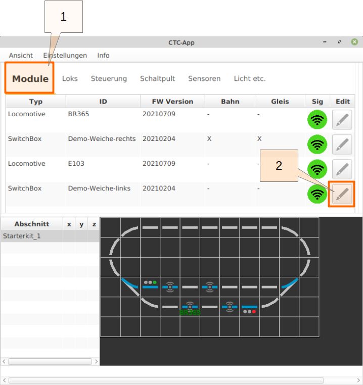
Selecting “Change Config” opens the “Edit Control Box Configuration” window.
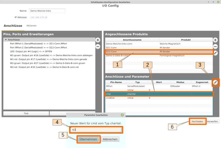
- In the “Connected Products” section, select “D22-Conn.”
- In the “Connections and Parameters” section, select the “dist” row.
- Click the edit pencil icon.
- Now enter the correct distance (in cm) from D21 to D22. In this setup, the distance between the two IR-balises is assumed to be 43 cm.
- Click “Apply” to complete the input and return to the “Edit Control Box Configuration” window.
- Click “Upload.”
Run Sensor Calibration
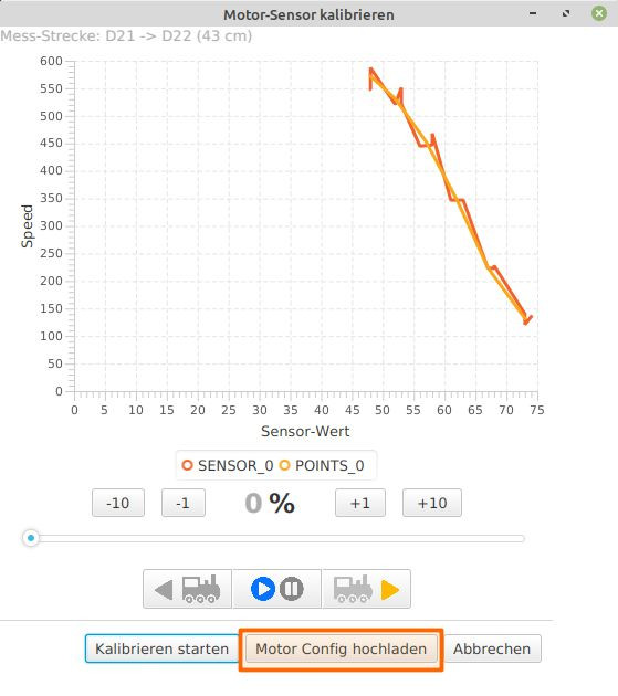
With this preparation, the sensor calibration of a locomotive can be carried out. The CTC app performs a series of measurements, with the locomotive traversing the measurement track at different speeds. The starting speed must be manually set by the user. The actual measurement cycle is carried out automatically by the CTC app, requiring no further intervention. The measurement track is traversed multiple times, with the speed increasing after every three rounds. The progress of the measurements can be tracked in the recorded measurement data graph.
In the main window of the CTC app, prepare the track for the locomotive:
- Set “Demo-turnout-left” to “Turn.”
- Set the “Demo-S-Track-B” signal in the station track to “Proceed.”
- Set “Demo-turnout-right” to “Turn.”
- Select the E103 locomotive and click “Edit” in the row.
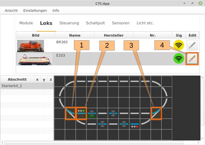
The configuration window for the locomotive opens, where you click “Calibrate Sensor.”
- The CTC app measurement cycle should start at the lowest possible speed for the locomotive. This must be set by the user. Typically, this value should be between 10 and 20 percent. For the locomotive used here, an exceptionally higher value of 35% must be set.
- By clicking “Start/Stop,” the locomotive sets off. The locomotive should run for some time, giving the opportunity to check the set minimum speed and adjust it if necessary.
- Click “Start Calibration” to start the measurement cycle, which runs autonomously.
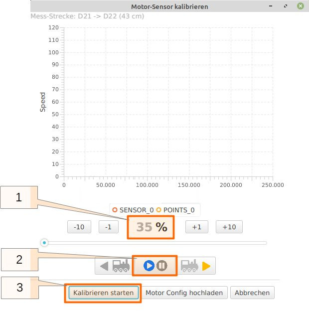
Once the locomotive has traversed the measurement track three times, the app automatically increases the speed by 10% increments. The track is then traversed three more times. This continues until the speed exceeds the 80% mark. In the “Calibrate Motor Sensor” window, the progress of data collection and analysis can be monitored.
When the measurement cycle is complete, the locomotive stops, and by clicking “Upload Motor Config,” the calibration values calculated by the app are transferred to the locomotive module, making them available for operation.
