Setting the Motor
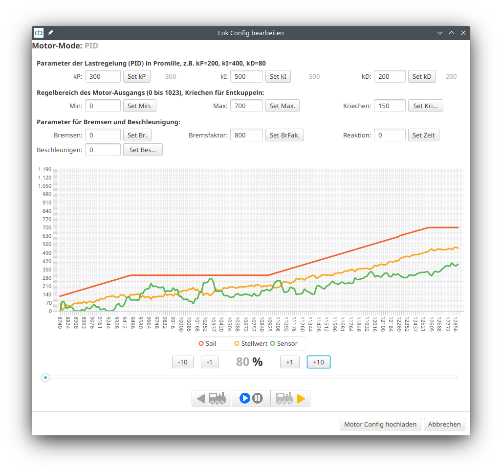
In this dialog, you can optimize the parameters of the motor control of a CTC locomotive module using live data. The locomotive continuously transmits the value of the motor sensor, the target value and the control value calculated by the PID controller. As long as all three values are 0, the diagram is “frozen”.
The displayed parameters belong to the currently selected operating mode (Motor Mode) of the locomotive. The parameters kP, KI and kD are only relevant in the “PID” motor mode and are ignored in “direct” motor mode.
When you click on the respective set button, the value to the left of it is directly transferred to the locomotive and remains there until the locomotive is reset. It is only when you click on “Upload Motor Config” that your settings are permanently saved.
Parameters of load regulation (PID controller):
- kP determines how directly the motor reacts to changes to the sensor. A value that is too high leads to jerky driving behavior, a value that is too low means that it takes a very long time for the motor to react to a changed target or sensor value.
- kI determines how strongly the motor reacts to the sum of all target value deviations.
- kD determines how strongly the motor reacts to the difference between the current and previous sensor.
- The sample rate can only be set directly in the cfg.xml and should remain at the default of 20 ms.
Control range of the motor output:
- Min and Max define the regulation range of the motor (0..1023). This allows you to exclude the lower range in which the motor does not rotate and limit the maximum speed.
- With Crawl you set the crawling speed, which is driven when uncoupling (“coupling waltz”) as well as the target speed for decelerating to minimum speed.

Parameters for braking and acceleration:
- Brakes is the acceleration constant for braking processes (in mm/s²). The specified value is given as positive and is multiplied by -1 in the locomotive. If the value is 0, the default value of 250 is used.
- Acceleration is the constant for acceleration processes (in mm/s²). If the value is 0, the default value of 250 is used.
- Brake factor is divided by 1000 and increased by 1 and used as an amplification factor during target braking. In the example (800), it is therefore multiplied by 1.8. By increasing the braking factor, the dip at the end of a braking process can be reduced. Too strong a braking factor leads to a brake curve that is bent downwards.
- Reaction specifies the time in milliseconds during braking until the retardation by the motor takes effect. This parameter only works from Firmware 20230609 (CTC-App 4.17).
Note: As long as the Setting the Motor dialog is open, the locomotive sends a rather large number of unsynchronized data packets for the diagram. This increased data traffic can lead to more frequent losses of data packets (#Msg.Miss in the Statistic Display).
Optimization of braking parameters
For the optimization of the target braking, I use a loop course with a signal before which the locomotive is stopped using 2 balises. The locomotive is in front of the red signal and has 70% set as its speed in the example. Then the signal is opened and as soon as the locomotive has started, it is closed again.
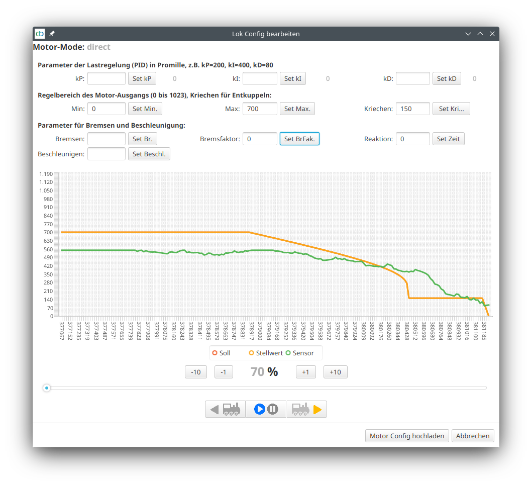
In the following example, you can see the locomotive arriving with 70% (700) (Piko BR 147), then the braking process up to the minimum speed (parameter “Creep” 150), a short time at minimum speed, and on the far right the stop. In the first try, braking factor and deceleration are set to 0:

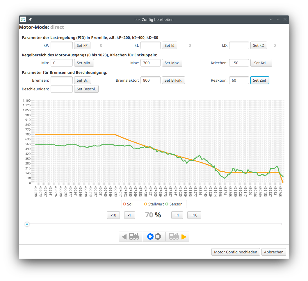
Now the braking curve was optimized and experimentally determined as 800 for the brake factor and 60 for the reaction as optimal values:

Note: Those who want to know in detail will find the “Motor-Setup.csv” data transmitted during the measurement in their user directory. This can be opened with Excel or LibreOffice, for example, and can be evaluated in detail there.


