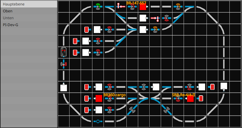
The Track Diagram Control Panel allows you to operate turnouts via a schematic representation of the model railway. Track sections are composed of individual (partial) track plans and saved as a “model railway.” The track plans and the model railway are each stored in a CTC-Turnout Module or a CTC-IO Module.
This means a track plan can be created for each contiguous part of a model railway (module, segment) and stored on that part.
The model railway and its components are automatically loaded as soon as the corresponding CTC module connects.
To learn how to use the Track Diagram Control Panel and what the displayed symbols mean, see Chapter 1.6 – Track Diagram: Switching and Status Indicators.
Before a model railway with its track sections can be created, the individual (partial) track plans must first be designed.
A track plan can be used in any number of track sections. However, a turnout, signal, balise, etc., can only be placed in exactly one track plan.
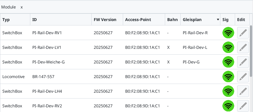
To check which modules already have a track plan or a model railway, open the Module List (or the Configurator). A checkmark appears under “Railway” if a “model railway” is stored on the module. For modules with a track plan, the name of the track plan is displayed in the “Track Plan” column. In the following example of our exhibition layout, a model railway is stored on two modules, and a track plan is stored on three modules: