This text describes how to configure the turnout modules to assign an action to the IR-balises. It is assumed:
- the track layout is set up,
- the signals are wired to the turnout modules,
- the IR-balises are wired to the turnout modules,
- the power supply is complete,
- the turnout modules have been reset,
- the turnout drive is connected and
- the IR-balises are connected.
As a reminder: The wiring for each of the turnout modules is done as follows:
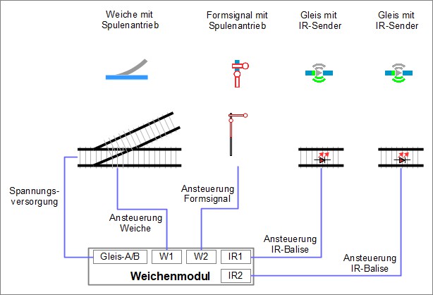
So far, the following has been completed:
- The wiring is done and
- the “products” (turnout drive, semaphore signal, and IR-balises) are connected to their respective ports/pins on the module.
Assign Action to IR-Balise
Basic Idea
The basic idea for the following configuration is: When a locomotive approaches a signal, it should receive information whether the signal is set to “Stop” or “Go” and how far the locomotive is from the signal. This information is sent to the locomotive via the IR-balises embedded in the tracks.
- At “Go”, the locomotive continues to run unchanged.
- At “Stop”, the locomotive should slow down and stop before the signal.
Here again is the schematic layout of the setup:
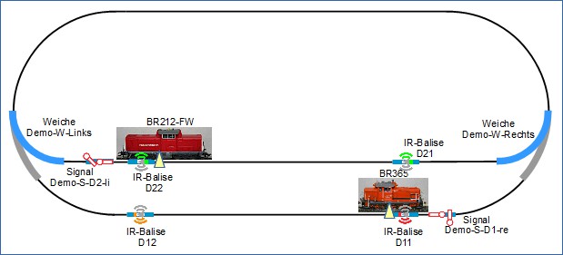
In the direction of travel of the locomotives, 2 IR-balises are installed in front of each signal. For example, suppose that the shunting locomotive BR365 is traveling towards the signal “Demo-S-D1-re” and the signal is set to “Stop”. The sequence is as follows:
- Travels through “Demo-W-Links”.
- Travels over IR-balise D12.
- The information sent by D12 has the following content: “This is IR-balise D12, the distance to the upcoming signal is 80 cm, the signal is set to ‘Stop’. “.
- The locomotive slowly reduces its speed so that it would come to a stop in 80 cm.
- Since the distance between D11 and D12 is less than 80 cm, D11 is crossed at a significantly reduced speed.
- Travels over IR-balise D11.
- The information sent by D11 has the following content: “This is IR-balise D11, the distance to the upcoming signal is 0 cm, the signal is set to ‘Stop’ “.
- The locomotive immediately reduces its speed and comes to a stop.
Implementation
The following describes the configuration of the module in “Demo-W-rechts” for the IR-balises D11 and D12.
When connecting the IR-balises, the CTC-App has already internally set up some configurations.
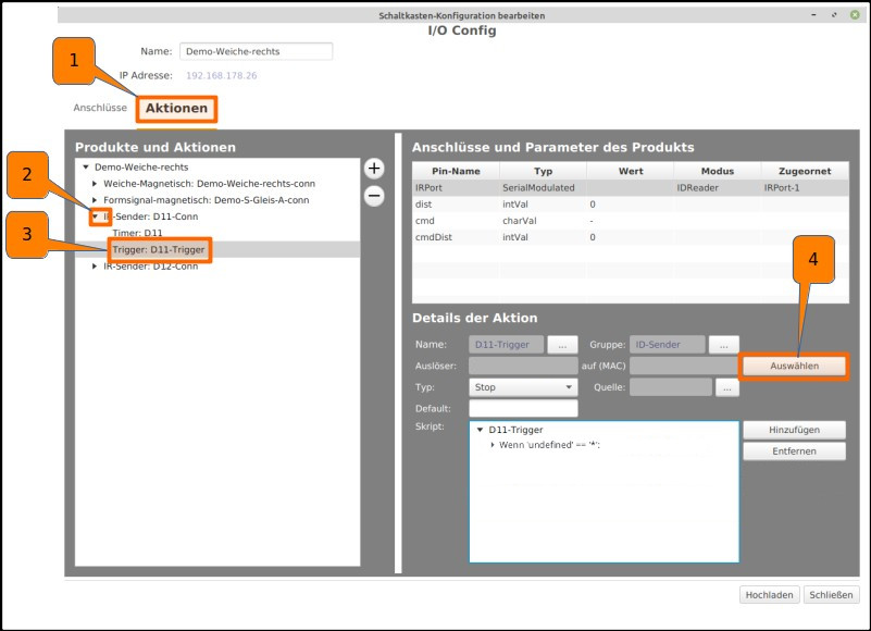
Clicking on “Settings” and “Configurator” opens the configurator. Clicking on the pencil icon in the SwitchBox row with the ID “Demo-W-rechts” opens the window “Edit Switch Box Configuration”.
- Clicking on the “Actions” tab opens the corresponding window.
- Clicking on the TRIANGLE NEXT TO “IR-Balise: D11-Conn” opens further options.
- Clicking on the “Trigger: D11-Trigger” field opens further options under “Action Details”.
- Clicking on the “Select” field opens the window “Choose Trigger”.
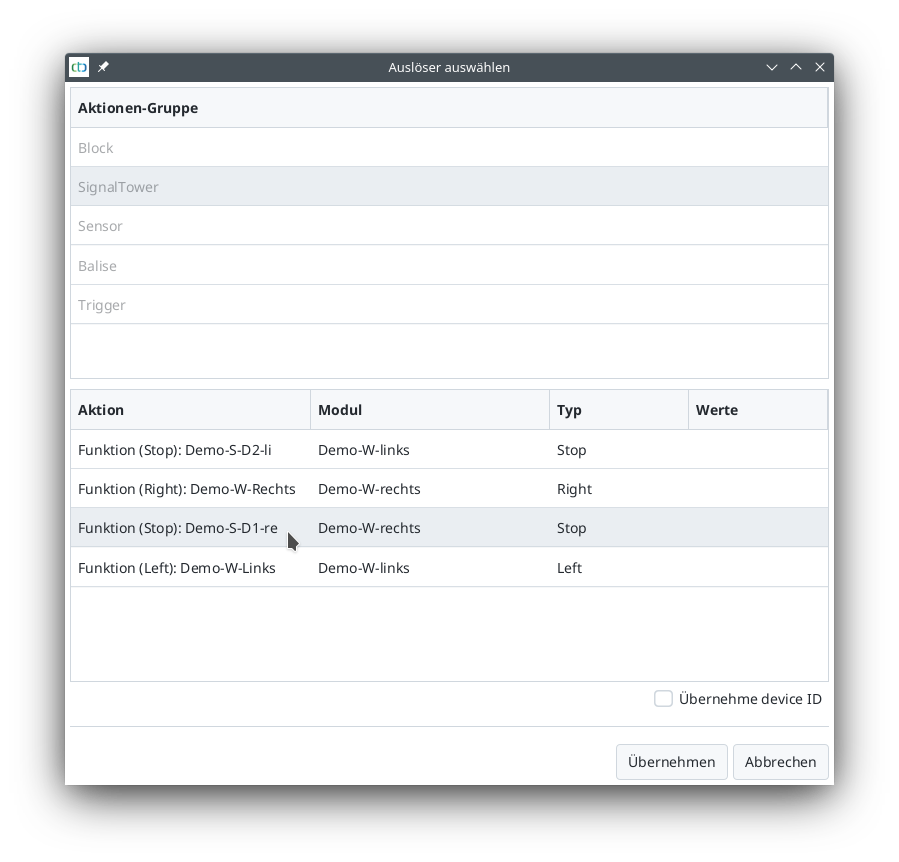
Continuing with choosing the trigger:
- Under “Action Group”, select “SignalTower”,
- under “Action”, select “Demo-S-D1-re”,
- clicking on “Apply” closes the window.
For the balise directly in front of the signal, the action details are already appropriately configured: In all cases (‘*’), the command remains unchanged to reflect the signal state (param[cmd]=’?’).
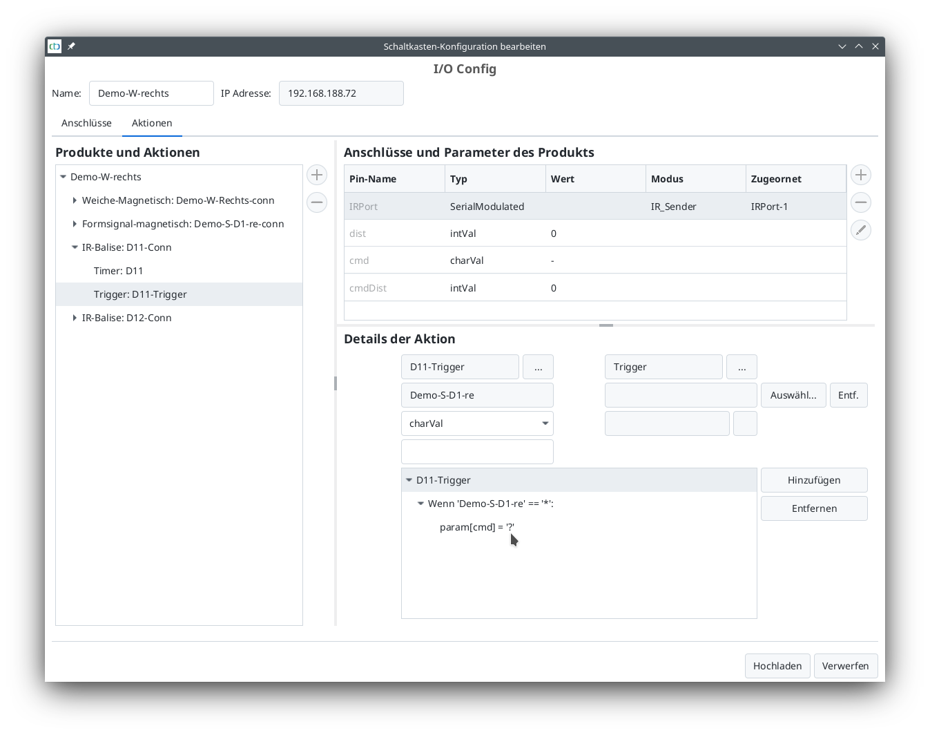
The IR-balise D12 is configured almost the same as D11. However, if the signal is red, the locomotive should not stop immediately but instead slow down to minimal speed over the distance to balise D11.
- Clicking on the TRIANGLE NEXT TO “IR-Balise: D12-Conn” opens further options.
- Clicking on the “Trigger: D12-Trigger” field opens further options under “Action Details”.
- Clicking on the “Select” field opens the window “Choose Trigger”.
- Under “Action Group”, select “SignalTower”,
- under “Action”, select “Demo-S-D1-re”,
- clicking on “Apply” closes the window.
- In the “Action Details” section: Clicking on the TRIANGLE NEXT TO “D12-Trigger” opens further options.
- In the “Action Details” section: Clicking on the TRIANGLE NEXT TO “If ‘Demo-S-D1-re’ == ‘*’” opens further options.
- Clicking on the line “If ‘Demo-S-D1-re’ == ‘*’” displays the parameters of the If-command on the right.
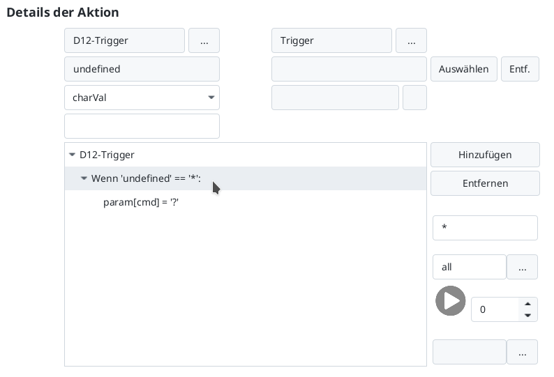
The special case “Signal red” needs to be treated first. Which letter is assigned to this state can be found in the manual in Chapter 4.5 “Config - Edit Script”.
Alternatively, one can simply view the config of the signal.
- Clicking on the TRIANGLE NEXT TO “Semaphore signal magnetic: Demo-S-D1-re-conn” opens further options.
- Clicking on “Function (Stop): Demo-S-D1-re” shows the action details.
- Clicking on the script “Switch to Hp0_Bar (‘h’)” shows the details of the state with the letter ‘h’. The symbol next to the script window speaks more than a thousand words.

Back to the trigger, the state ‘h’ can now be entered in the If-command.
- Clicking on “Trigger: D12-Trigger” switches back to the trigger of balise D12.
- Clicking on the line “If ‘Demo-S-D1-re’ == ‘*’” displays the parameters of the If-command on the right.
- Clicking in the field below the Remove button allows entering the letter ‘h’.
- In the field below, enter a name corresponding to the condition, e.g., “stop”.
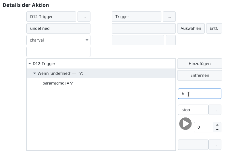
Now specify what should happen at ‘h’:
- Clicking on “param[cmd] = ‘?’” displays the parameters of the “param” command on the right.
- Clicking the button next to ‘?’ opens the command selection.
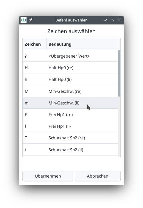
In all other cases, the signal state is taken over again. A new If-command needs to be added for any state.
- Click on the top line in the script area (“D12-Trigger”).
- Then click on “Add”.
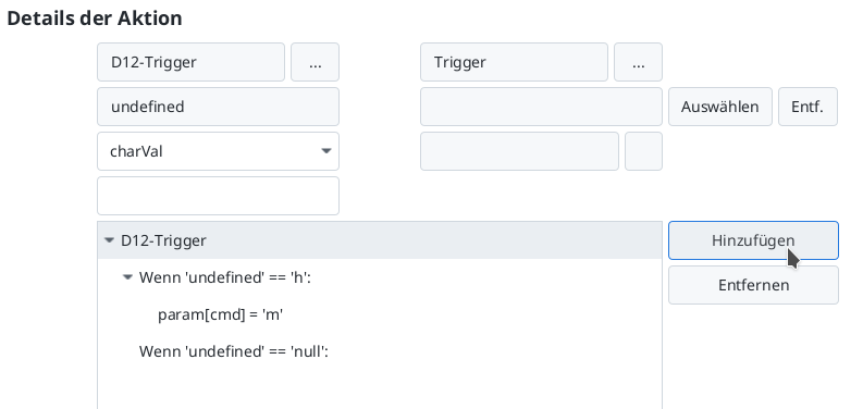
- Enter the asterisk (‘*’) as the condition for the If-command.
- In the field below, enter a name corresponding to the condition, e.g., “otherwise”.
- Change the script position below from 0 to 1.
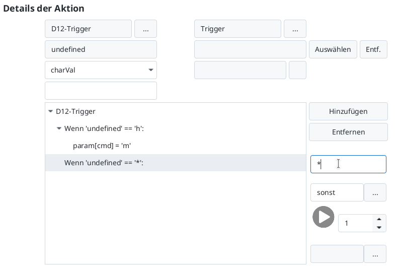
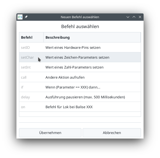
Next, add the command for the new If-command.
- Click on “Add” - the “Select New Command” window opens.
- Click on the “setChar” command.
- Then click on “Apply”.
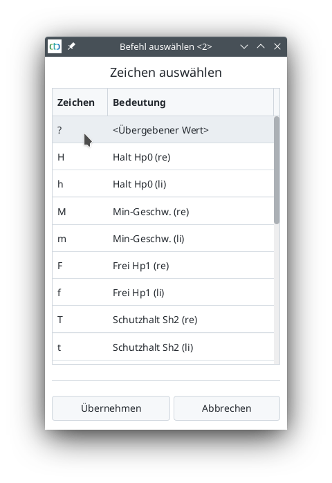
The line “param[?] = ‘?” is selected. Now specify that “cmd” should take over the state of the signal (‘?’):
- From the list under “Remove”, select the value “cmd”.
- Click the button on the left below the selection list - the “Select Command” window opens.
- Select the line ‘?’.
- Click on “Apply”.
The script for the trigger of balise D12 is now complete:
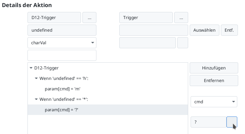
What is still missing is the distance for braking. Since this is independent of the signal state, it is set fixed instead of changing it in the script.
- Click on the line “cmdDist” under “Connections and Parameters of the Product”.
- Click on the pencil icon to the right of the selected line.

Now balise D12 is also completely configured:
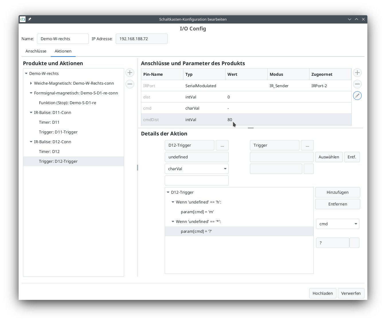
Clicking on “Upload” completes the changes to the triggers of both balises D11 and D12.
Configure Second Turnout Module
The second turnout module is configured the same way as the first turnout module. It has exactly the same connections: a turnout drive, a semaphore signal with magnetic drive, and two IR-balises. When selecting the products, note that this is a turnout that turns to the left.
The assigned names are:
- Module: Demo-W-Links
- Signal: Demo-S-D2-li
- IR-balises D22 (stop) and D21 (braking)
The configuration of the turnout modules is complete.


