This text describes the configuration of the turnout modules for the starter set. In choosing words, note:
- “Wiring” refers to the electrical connection, that is, the cables, lines, connectors.
- “Connection” or “connecting” refers to the software-technological connection, that is, the configuration of the module to which the respective component (turnout with coil drive, semaphore with coil drive, IR-balises) is wired.
It is assumed:
- the track layout is set up,
- the turnout modules are installed in the turnouts and the coil drive of the turnouts is connected,
- the signals are wired to the turnout modules,
- the IR-balises are wired to the turnout modules,
- the power supply is complete,
- the turnout modules have been reset,
- the turnout drives are wired and
- the semaphores are wired.
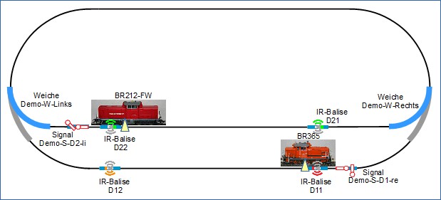
As shown right at the start, this is the track layout:
As a reminder: The wiring for each of the turnout modules is carried out as follows:
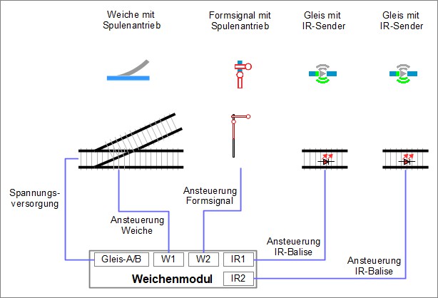
Applied to the track layout, this means for the wiring:
- The semaphores “Demo-S-D2-li” as well as the balises “D21” and “D22” are wired to the module of the turnout “Demo-W-Links”.
- The semaphore “Demo-S-D1-re” and the balises “D11” and “D12” are wired to the module of the turnout “Demo-W-Rechts”.
The “wirings” of the IR-balises are now being “connected”.
#
Connecting the IR Balise Product
In the “Modules” window, click on the “Edit” symbol for the ID “Demo-turnout-left”, the “Edit Switchbox” window will open. In the “Edit Switchbox” window, the “Edit Switchbox Configuration” window is opened by clicking on the “Change Config” button:
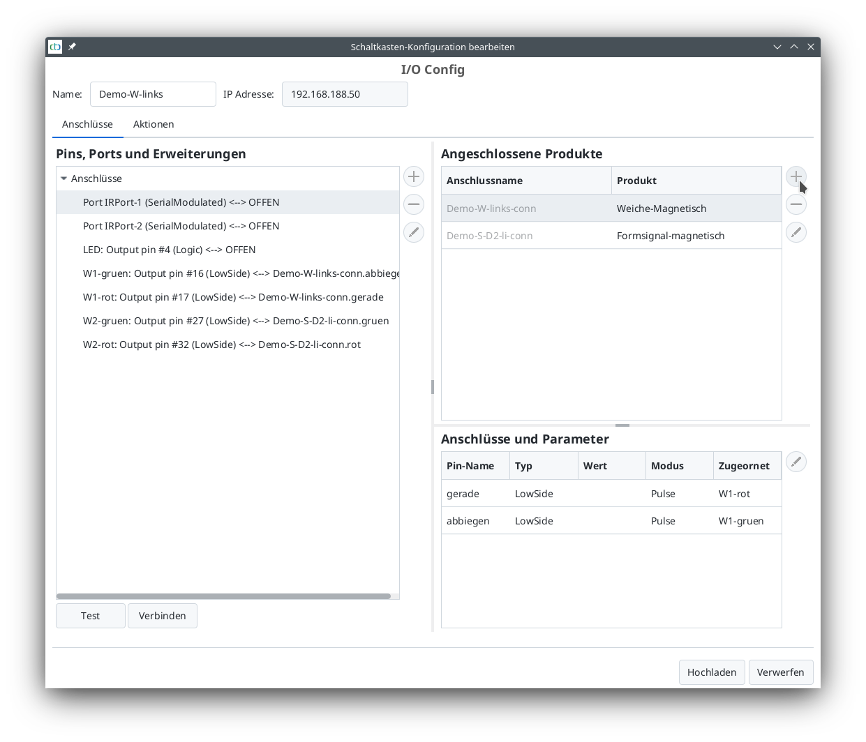
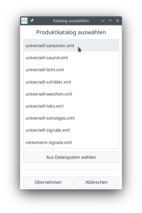
Here, in the “Connected Products” section, click on “+” (see mouse pointer) to open the list of product catalogs.
- The “universal-sensors.xml” catalog is selected and
- opened for further work by clicking on “Apply”.
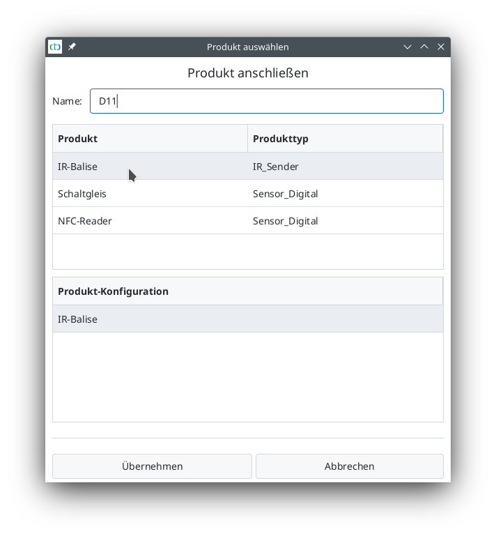
The “universal-sensors” catalog has been selected. From this catalog, the “IR-Balise” is selected and named:
- Enter “D11” for “Name”
- Select “IR-Balise” as the product and
- Click on “Apply” to prepare the IR-Balise for connection.
After clicking on “Apply”, you will be returned to the “Edit Switchbox Configuration” window.
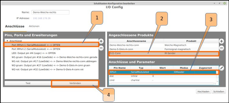
The first IR-Balise D11 will be connected:
- Select “Port: IRPort-1 (SerialModulated)” under “Pins, Ports and Extensions”,
- “D11-Conn” is selected under “Connected Products”,
- “IRPort-1” is selected under “Connections and Parameters”, and
- Click “Connect” to confirm the connection.
The same is done with the second infrared port “IRPort-2:
- Double-click to open the “universal-sensors.xml” product catalog,
- Select IR-Balise product,
- Enter “D12” as the name and confirm.
- In the “Edit Switchbox Configuration” window, select “Port: IRPort-2 (SerialModulated)” under “Pins, Ports and Extensions”,
- “D12-Conn” is selected under “Connected Products”,
- “IRPort-2” is selected under “Connections and Parameters”, and
- Click “Connect” to confirm the connection.
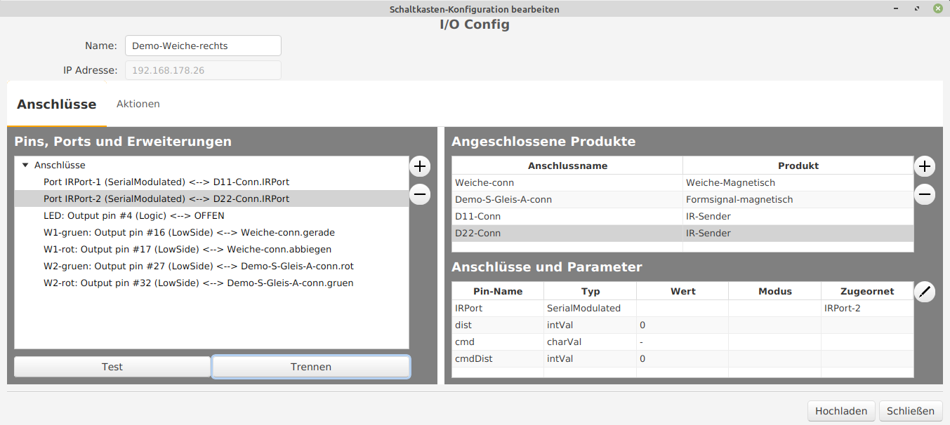
The first turnout module named “Demo-turnout-right” is now fully connected and has the following connected:
- a magnetic turnout drive,
- a magnetic signal drive,
- an IR-Balise D11, and
- an IR-Balise D12.