


In the following, it is assumed that the CTC layout is set up and configured according to the descriptions for the starter set.
During the switch-on sequence of the CTC components, it must be noted that the Wi-Fi router must be switched on and ready for operation first. The railway layout is then switched on.
The CTC app finds the PI-Rail Wi-Fi and connects to the CTC modules. The configuration of the modules is read out. In the chosen example of the starter kit, the CTC app has found a locomotive (BR365), two turnouts, and two semaphore signals. The configuration of the locomotive was read out, which gives the respective image of the locomotive, its name, and further configuration information, which will be looked at later. The track plan - here called “Starterkit_1” - is stored in one of the configured turnout modules (Demo-W-right) and was also read out. It also contains information about the semaphore signals.
Once the CTC app is started, the initial screen shows the “Module” window:

The window with the tabs for the selection “Modules, Loks, Control, Control panel, and Sensors” allows access to the individual function groups:
- Modules: The list of all found modules and their most important parameters appears here. From here, their configuration can be directly called up.
- Loks: Here all found locomotives appear, the locomotive highlighted in grey is the selected locomotive (see also “Control”).
- Control: Here the control panel of the selected locomotive appears (see “Loks”).
- Control panel: Here are displayed the controllable modules of the track diagram that perform switching functions, i.e. turnouts, signals, etc. The track diagram also includes the IR balise markers.
- Timetables: Here, timetables for automated train operation are edited and called up.
- Sensors: Here all sensors are shown. In this case, each locomotive has an infrared sensor. The sensors receive the messages from the IR balises built into the track.
Through the menu bar, with “View” and “Show Left Panel,” an additional control panel is opened. The windows of the panels can be moved so that they are clearly visible. The selection of “Control” for the left panel and “Control panel” for the right panel results in:
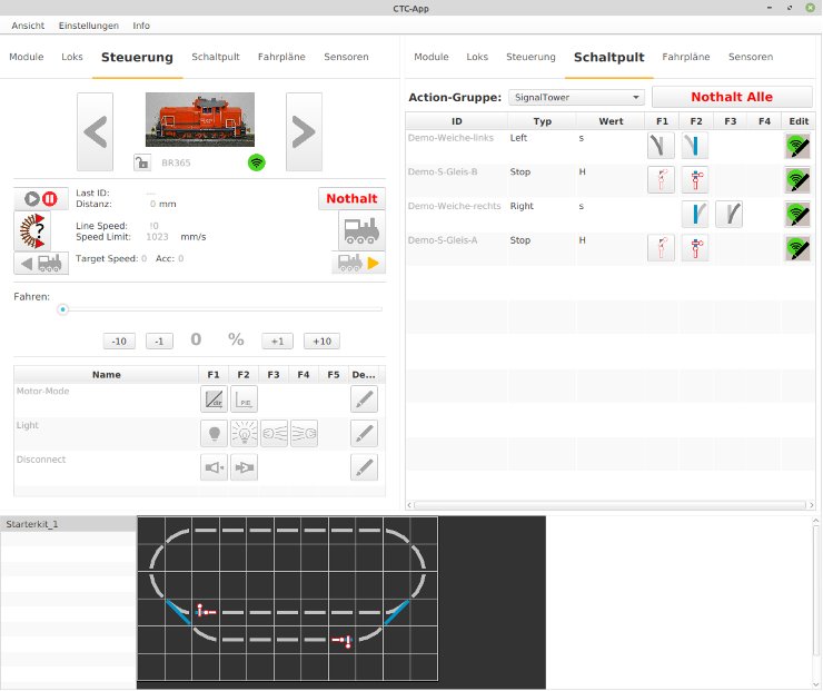
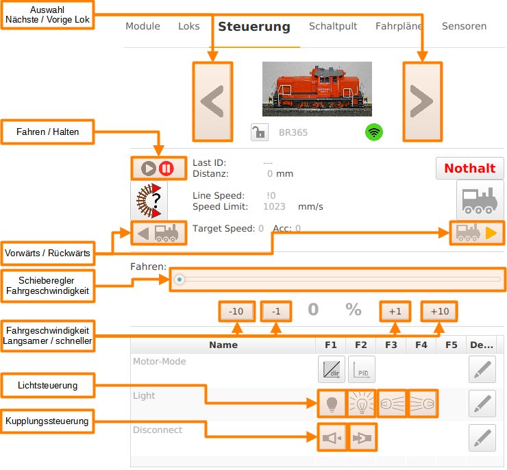
The “Control” tab offers control over the selected locomotive (in “Loks” selection tab):
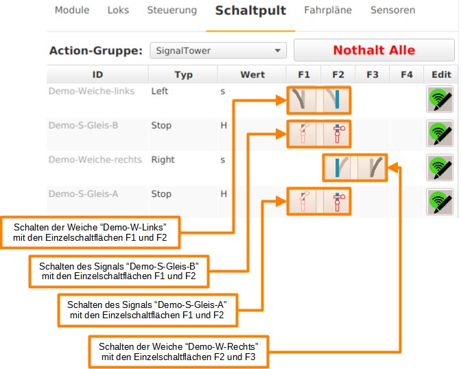
The “Control Panel” tab provides access to turnouts and signals (and optionally other drives if available).
The switching functions are performed with the individual switches as follows:
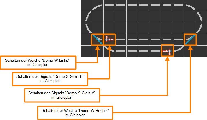
Turnouts and signals can alternatively also be switched directly in the track diagram:
On the first operation of the layout, the BR365 locomotive can now run, the control of the turnouts allows the entry into the station track or the ride on the passing track. Also, the signals can be switched. It is noticeable that the locomotive does not react to the position of the signals, the train must be stopped manually in the “Control” window or the continuation of the journey has to be initiated.
Further configuration steps are necessary for the locomotive to slow down in front of a signal set to “Stop” and come to a standstill. The IR balises are used for this.