


Introduction
A starter set from CTC, in conjunction with an extension set, allows the assembly of a small track layout, with which the essential skills and capabilities of CTC can be tested and used. Although this is “just” a starter set, the layout is built in such a way that it can be expanded. These extensions will be described in the course of additional documentation. The construction of the starter set takes into account the extensions already in the assigned names, and this will be pointed out at the relevant points.
This document describes the starter set plus extension set for Märklin C track. The modules must be installed and configured into the locomotives and turnouts. If a starter set is used with already built-in CTC locomotive and turnout modules, the steps for installation can be skipped. Additionally, two semaphore signals with magnetic drive are used. The following topics will be covered initially:
- Installation and electrical connection of modules (locomotives, turnouts) (Chapter 2),
- Layout construction (Chapter 3),
- Configuring turnout modules for the operation of turnouts and semaphore signals (Chapter 4),
- Creating the track diagram (Chapter 5), and
- First commissioning of the layout (Chapter 6).
The layout to be built is similar to the one described in the article A CTC Model Railway is born. The associated application software, CTC-App, can be installed and run under both Windows, Linux, and Mac. Possible limitations regarding the operating systems must be considered. The various Linux distributions can indeed show divergent behavior. More information about the supported versions can be found in the Operator’s manual Chapter 2.
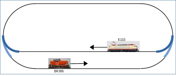
The layout floor plan consists of an oval with a station as a stop. For the train operation, it is assumed that one locomotive runs clockwise and another locomotive runs counter-clockwise. With the CTC-App, the turnouts are switched, and the locomotives are driven.
Once the locomotives have been run on the layout for the first time, the expansion of the layout can commence:
- Build in IR balise (formerly called “IR transmitter”) into the tracks and configure for operation (Chapter 7),
- Supplement track plan with IR balise (Chapter 7),
- Calibrate the locomotive sensors (Chapter 9), and
- Carry out train operation with signals and IR balise (Chapter 10).
The following functionality is implemented: when a signal is set to “stop”, the locomotive slows down, travels up to the IR balise in front of the signal and stops. The functionality is expanded to include the balise.
For the designations of the balise, signals and turnouts, names are chosen that are useful or even necessary for block operation and train automation (detailed explanation see “Outlook”).
Following this, automated train operation is introduced. With this configuration, a small “timetable” is created for one locomotive:
- Entry into the station area with the locomotive slowing down (Chapter 10).
- Slow travel into the station and stopping (Chapter 10).
- After the predefined waiting time, the locomotive continues its journey, travels a lap and again enters the station area (Chapter 10).
Outlook
For further expansion of the layout, the starter set will be extended:
- A turnout and further tracks will enable a “terminal station”.
- The block operation will be expanded with additional IR balises.
- Some blocks will receive semaphore signals.
- Appropriate CTC modules are required for the IR balises, semaphore signals and the turnout.
With the help of the mentioned expansions, the operation will be extended to the terminal station. The following illustration shows the schematic track diagram in a very extensive expansion phase. It will be indicated which of the individual balises, signals, turnouts, and tracks are used in the respective setup examples.
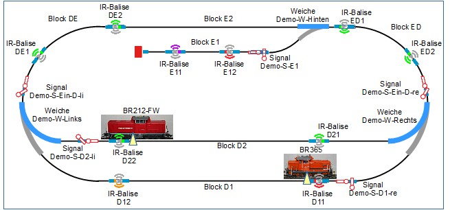
Names are chosen for the designations of the tracks and blocks, as well as for the balises, signals, and turnouts, which are meaningful or even necessary for block operation and train automation.
- There are two station areas, these are designated with “D” and “E”. This results in the following blocks:
- Block D1 is the “throughway area” of “station area D”.
- Block D2 is the “stop area” of “station area D”.
- Block E1 is the “stop area” of “station area E”, this station is designed as a terminal station.
- Block E2 is the “throughway area” of “station area E”.
- Block DE connects Block D with Block E. The naming adopts the direction of a locomotive in a clockwise direction.
- Block ED connects Block E with Block D. The naming adopts the direction of a locomotive in a clockwise direction.
- Balises are numbered in a clockwise direction and assigned to a block.
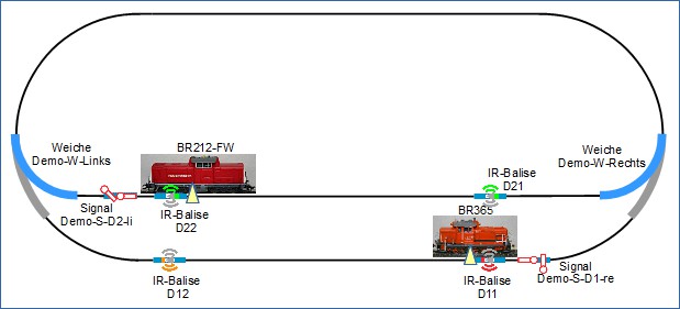
- Balises D21 and D22 belong to Block D2 and are closely related to the position of the corresponding signal Demo-S-D2-li.
- Balises D11 and D12 belong to Block D1 and are closely related to the position of the corresponding signal Demo-S-D1-re.
- Balises DE1 and DE2 belong to Block DE and are closely related to the position of the corresponding signal Demo-S-Ein-D-li.
- Balises ED1 and ED2 belong to Block ED and are closely related to the position of the corresponding signal Demo-S-Ein-D-re.
- Balises E11 and E12 belong to Block E1. Balise E12 is closely related to the position of the corresponding signal Demo-S-E1.
- Signals, like balises, are part of a block. Signals can be seen as “exit signals out of a block”
or as “entry signals into the next block” (in the direction of the moving train).
- Signal “Demo-S-D2-li” is an exit signal for Block D2, locomotive BR212-FW travels in a clockwise direction and later in a shuttle train operation.
- Signal “Demo-S-D1-re” is an exit signal for Block D1, locomotive BR365 travels counter-clockwise.