





Continuation from Part 1 .
The past two weeks were marked by planning the signals for the main station and tinkering with Märklin’s C-track.
The removable C-track
While this has nothing to do with CTC, we don’t want to keep it from anyone: As nice as C-track is for carpet model railroaders, it’s so annoying for permanent installations: It snaps together in a flash, but if you want to separate it again, you have to dismantle half the layout.
Peters father already cursed about it 20 years ago and got laughed at by Märklin support when he called to suggest removable C-track.
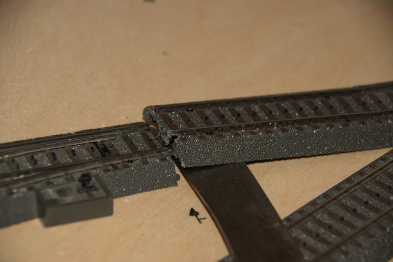
Well, removable C-track still doesn’t exist, but it can be made easily: Saw off the plastic clip and other protrusions at one end Use pliers to completely remove the connecting tabs File the end of the track slightly slanted downward At the point where the other track’s overhang comes, file a small notch
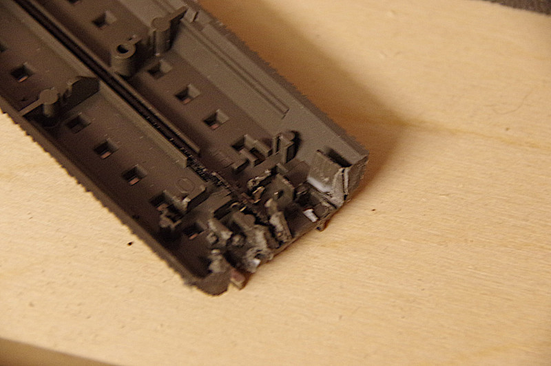
The lateral guidance is still surprisingly good, and when screwed down the track fits perfectly. With a knife it can be easily popped up at any time:
Light signals
After prolonged tinkering, we decided not to connect the departure signals to the CTC-Turnout-Modules. The deciding factor was our own advertising slogan: “Sensational reduction of wiring.”
So each departure signal gets its own CTC-Multi-I/O-Board, to which only the IR-balise directly in front of the departure signal is connected. The other IR-balise is connected to the CTC-Multi-I/O-Board for the departure signal at the other end of the track (for the opposite direction). Since the departure signals are equipped with 6 LEDs, the 8 connections of the I/O-board are sufficient.
We place the light signal about 20 cm away from the IR-balise. For the lateral spacing, we use Märklin’s overhead line gauge.
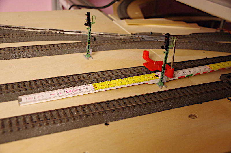
The CTC-Multi-I/O-Boards are mounted at the edge of the model railway segment, easily accessible from the front or back:
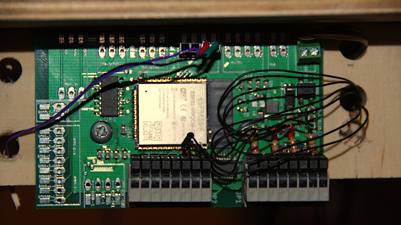
The first departure signal was successfully connected, configured, and tested with the CTC app.
To be continued...