





The IR beacons consist of infrared LEDs with a wavelength of 950 nm. Several LEDs are connected in parallel and equipped with a series resistor so that they only transmit a few centimeters. The series resistor must be dimensioned so that a maximum of 10 mA current flows at 3.3 V.
Upon request, we can also manufacture suitable IR transmitters for you.
Our kit is available with two different circuit boards, each with five 950 nm IR LEDs (e.g., Vishay TSUS 4300) and a 1 kOhm series resistor:
- 42 mm x 30 mm circuit board with LED pitch of 6.9 mm for H0 gauge including holes for snapping into Märklin C track
- 42 mm x 20.5 mm circuit board with LED pitch of 4.7 mm for N and TT gauge including 3 mm holes for screwing
The IR transmitters are available in two generations:
- The first generation has a 1 kOhm resistor
- The second generation has a 220 Ohm resistor, as newer CTC modules (e.g., CTC-Multi-IO-Board-4) already have 2x 470 Ohm resistors installed per IR beacon on the CTC module.
The two generations also differ in the supplied connector:
- The first generation has a 2-pin header
- The second generation has a cable with a 4-pin JST connector
Buy now: H0/C-track Gauge N/TT
Note: For garden railways, we recommend NFC instead of IR, see CTC-NFC-Reader
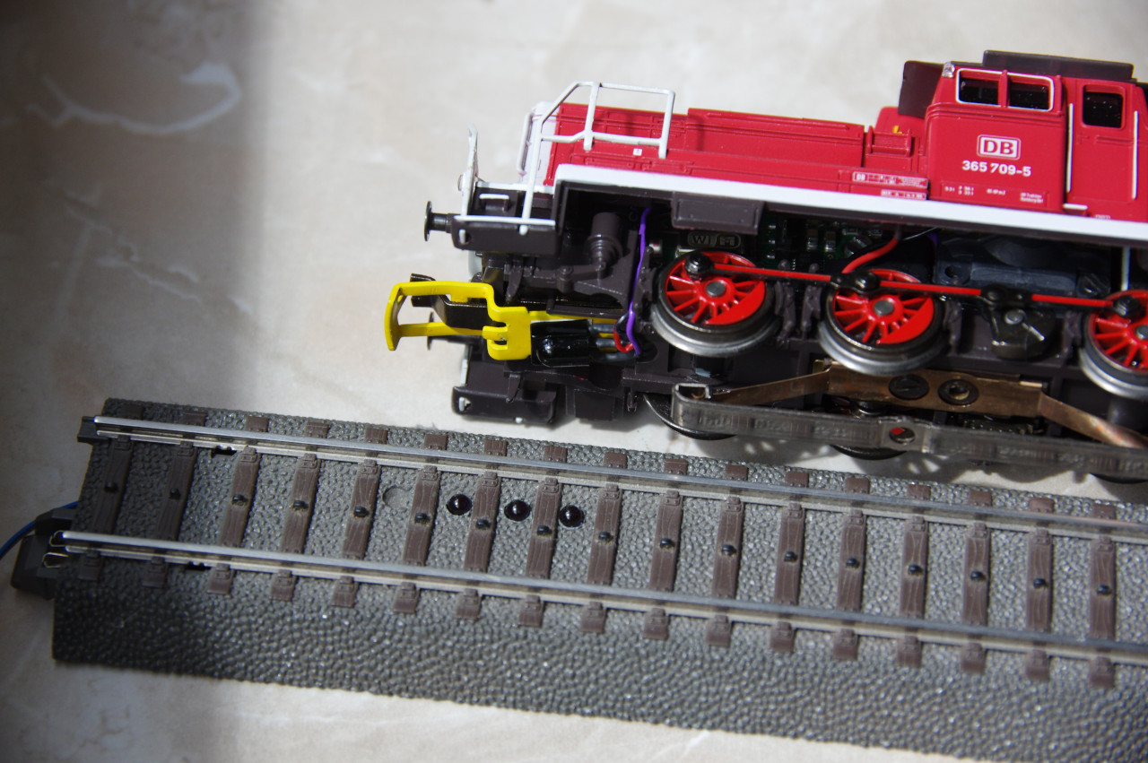
For our loco modules, the IR receiver is supplied together with a cable and suitable mini connector. To simplify installation, the IR receiver is supplied separately and must be soldered by you. In the image above, the IR receiver (black box) was glued under the front coupling (yellow).
IR beacon kit for C track
The following image shows the unprocessed C track and the parts of the IR beacon kit:
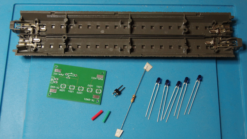
To build the IR beacon yourself, proceed as follows:
- Measure the circuit board and drill 5 holes in the track (3 mm diameter) where the mounting pins are located under the track:
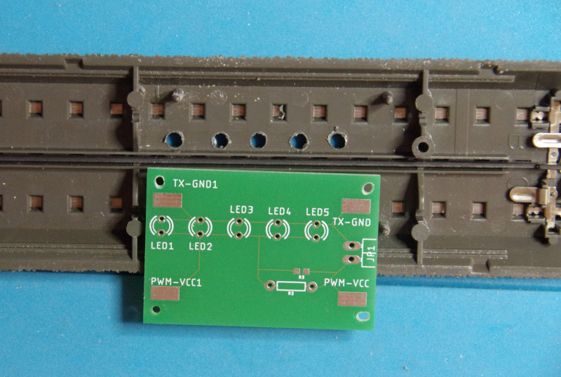
- Insert the IR LEDs into the designated holes in the circuit board (long leg toward the track center) and then insert both into the C track.
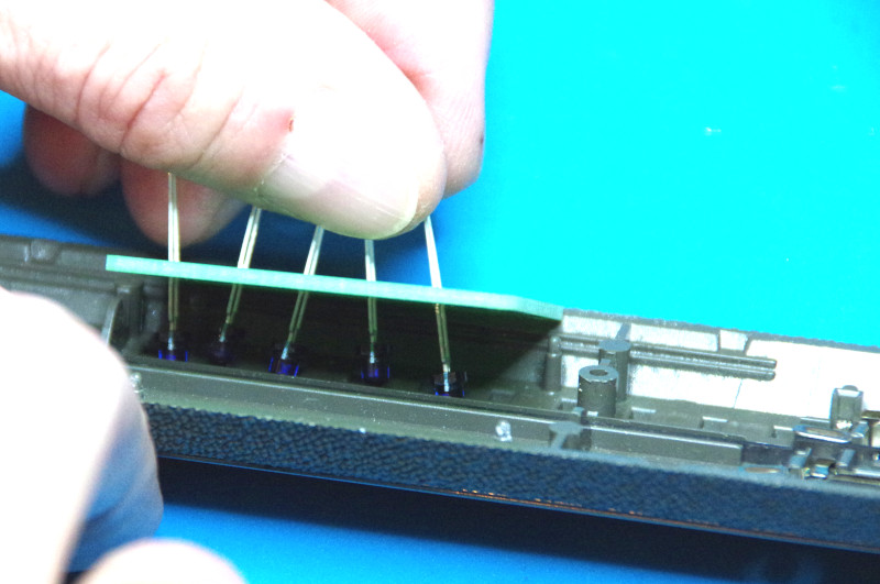
- Only now solder the IR LEDs.
- Remove the circuit board, insert the resistor and solder it.
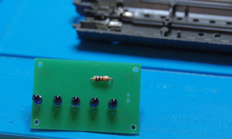
- Reinsert the circuit board and solder the connecting wires and connector:
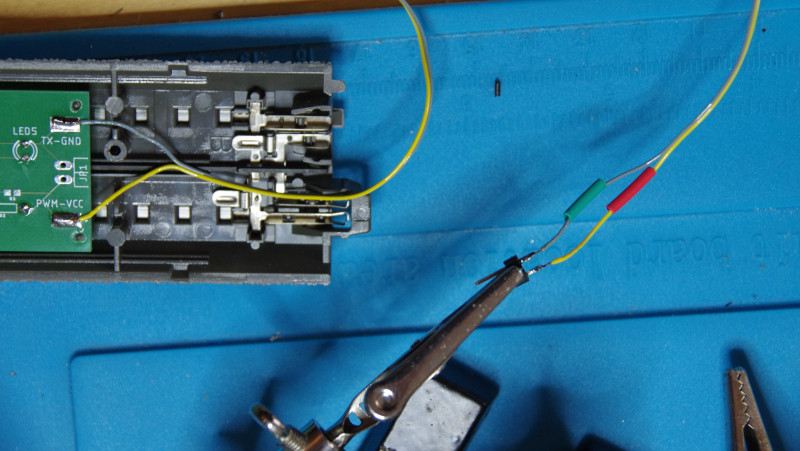 The positive pole (yellow cable with red heat shrink tubing in the image) goes to PWM-VCC and the negative pole (gray cable with green heat shrink tubing in the image) to TX-GND.
- You can check if all IR LEDs are working using your phone camera. To do this, connect the IR beacon to approximately 16 V DC (red heat shrink tubing to the positive pole). In your phone's camera app, you should now see the LEDs glowing purple (possibly shield against ambient light):
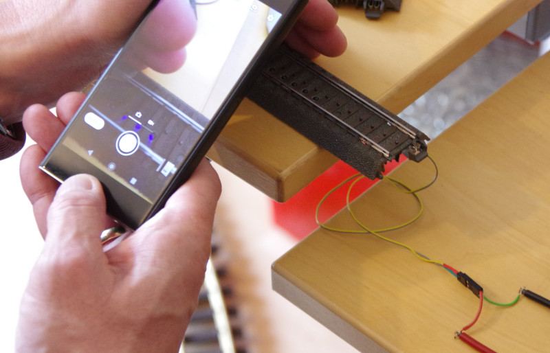 Since the LEDs only radiate upward at a fairly narrow angle, you may need to move your phone around to check all LEDs. If the IR beacons are connected to the CTC module (3.3 V), the phone camera will unfortunately no longer show anything.
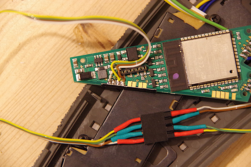
- The only thing left is to connect to a CTC-Turnout-Module or the CTC-Multi-IO-Board. The connector on the CTC module is marked with heat shrink tubing in the same colors (red, green):
IR beacon for C track without kit
You can of course also build an IR beacon without our kit, as shown in the previous instructions. We use Vishay TSUS 4300 LEDs (wavelength 950 nm) and the resistor is 1 kOhm.
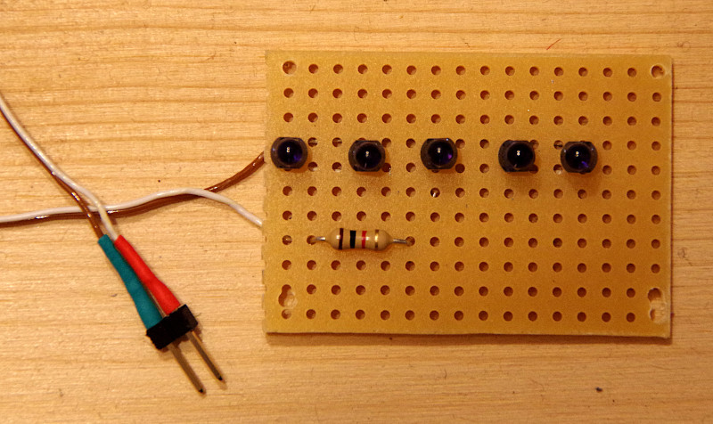
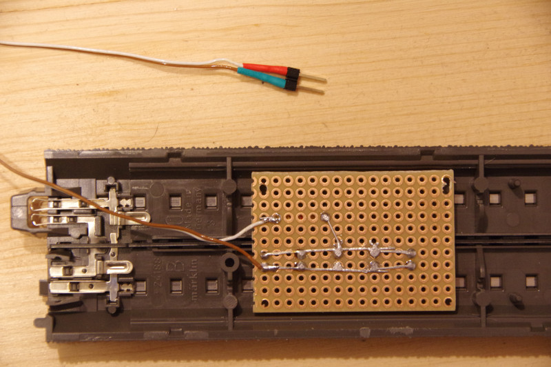
Sleeper spacing
To define a sensible grid for our mounting adapters, we measured the following values. Deviations occur on curves and compensation pieces. Feel free to send us values from other track systems, and we will add them here.
| Gauge | Track system | Standard straight | Deviation |
| H0 | Märklin C track | 7.5 mm | +/- 0.3 mm |
| H0 | Märklin K track | 7.6 mm | |
| H0 | Märklin M track | 7.6 mm | |
| H0 | Piko A track | 7.5 mm | |
| H0m | Bemo | ||
| TT | Tillig | 5.1 mm | |
| N | Fleischmann | 5.0 mm |