





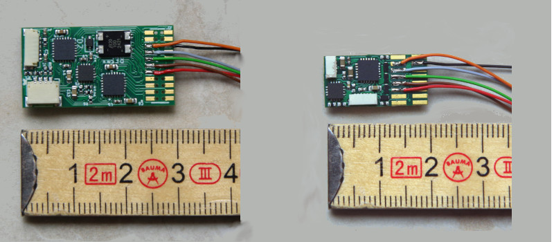
The image shows the CTC-Loco-Module-M3-DCC on the left and the CTC-Loco-Module-S3-DCC on the right.
The DCC variants of the CTC-Loco-Modules are optimized for controlling a DCC decoder. This allows you to keep the original DCC decoder in the locomotive and continue using original sounds with CTC.
The electrical properties are identical to the CTC-Loco-Module-M3 or CTC-Loco-Module-S3 . For the DCC signal, the motor output of the CTC-Loco-Module is used, meaning both have a DCC output power of 3.5 A peak (approx. 1.2 A continuous current).
In the overview "CTC-Loco-Modules " you will find more loco modules and links to installation instructions.
Connection
To install, the track connection of the existing DCC decoder is disconnected and the track is connected to the CTC-Loco-Module-DCC. The motor output of the CTC-Loco-Module-DCC is connected to the track input of the DCC decoder:
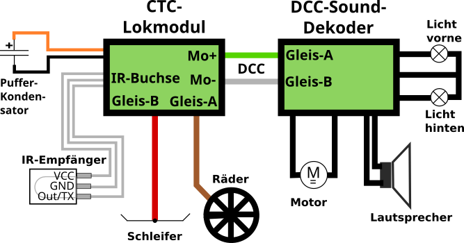
The IR receiver and capacitor are connected to the CTC-Loco-Module as usual.
IR Receiver
For each IR receiver, we provide you with a cable with a suitable 6-pin plug.
Buffer Capacitor
The cables for the buffer capacitor are already soldered to the CTC-Loco-Module:
- The positive pole (VBB) goes to the orange cable.
- The negative pole (GND) goes to the black cable.
Optionally, we can supply the CTC-Loco-Module-DCC already with a pre-soldered capacitor.
Pin Assignment and Dimensions
Details on pin assignment and dimensions can be found in the data sheets for CTC-Loco-Module-M3 or CTC-Loco-Module-S3 .