





The CTC-Loco-Module-M3 (medium) is optimized for locos from H0 gauge and is available in the following variants:
- with standard plug PluX22 ,
- with Märklin’s 21mtc interface ,
- with 8-pin plug-in board according to NEM-652 ,
- with 6-pin pin header according to NEM-651 ,
- with cables for track, motor, lighting and up to 6 AUX connections,
- for G gauge with PluX22 interface and cables for the NFC reader
- with cables for connecting a DCC decoder .
It is intended as a successor to doc/light/en//data_sheet/CTC-Lokmodul-PluX22.html, doc/light/en//data_sheet/CTC-Lokmodul-21mtc.html, doc/light/en//data_sheet/CTC-Lokmodul-H0a.html and doc/light/en//data_sheet/CTC-Lokmodul-H0d.html.
The variants with standardized plugs can be installed without soldering. For converting older (including analog) locos, you can use our CTC-Adapter-PluX22 or one of the cable variants.
| Property | Description |
| Optimized for | locos from H0 gauge with PluX22, 21mtc, NEM-651, NEM-652 or for soldering |
| Dimensions | 30 x 15.5 mm |
| Processor | Espressif ESP32 (ESP32 PICO Mini-02) |
| Input voltage | approx. 9 V to 24 V DC or digital current or AC (with support capacitor) |
| Motor output | 1x DC motor: continuous current approx. 1.0 A, peak 3.5 A |
| Switching outputs | 8x 500 mA half-bridge (F0L, F0R, AUX1 to AUX6) With PluX22, AUX7 is not connected |
| Total current max. | 2 A |
| Interfaces | SUSI3 classic, CTC IR receiver, train bus (e.g. SUSI3), 2x input, 2x GPIO |
| Online passive power | TBD |
| Boot current | 50 mA at 15 V |
Now buy: PluX22 21mtc NEM-652 NEM-651 Cables G gauge DCC
In the overview "CTC-Loco-Modules " you will find more loco modules and links to installation instructions.
The image shows the 21mtc, NEM-652 and PluX22 variants (from left to right):
Connection
Notes:
- When selecting the input voltage, please remember that motors, lamps, etc. connected to the CTC module must also be compatible with this voltage With PluX22, the AUX-7 connection is not used.
- With 21mtc and PluX22, the train bus can be used as a SUSI interface.
To connect:
- plug the CTC module onto the appropriate socket of the locomotive or solder the cables.
- if not already supplied, solder the buffer capacitor
- plug the optional CTC IR receiver or NFC reader onto the 8-pin socket on the CTC module.
The assignment of lighting and AUX connections to switches in the app can be freely configured (cfg.xml).
IR Receiver
We supply you with a cable with a suitable 6-pin plug for the IR receiver.
The socket on the module is a JST SM06B-SURS-TF. We also use this socket to flash the module via an FTDI cable. The pin assignment is as follows: 1-Reset, 2-Flash, 3-GND, 4-TX, 5-RX, 6-VCC.
Buffer Capacitor
The buffer capacitor (470 µF in the image) is soldered to the + and - contacts of the rectifier:
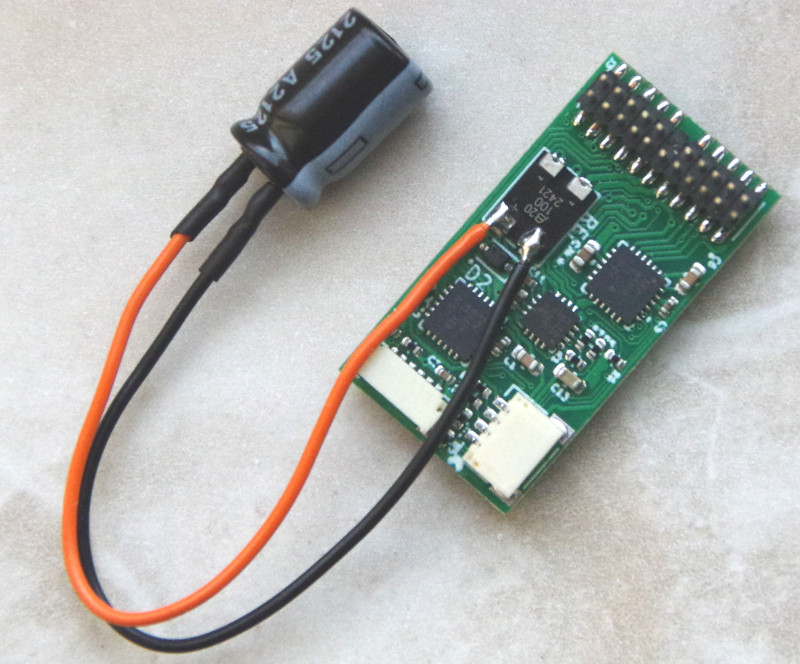
We can optionally supply the CTC-Loco-Module-M3 already with the capacitor soldered on.
Pin Assignment
Details on pin assignment and dimensions can be found in the respective standards (see above).
The cable variant is soldered to the contacts for the PluX22 plug:

The following diagram shows pin assignment and cable colors:
