





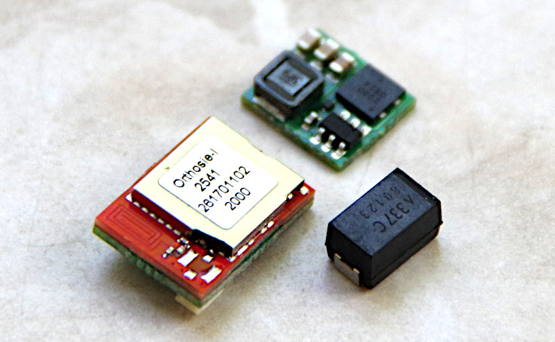
The image shows the XS3 loco module on the left front and the buffer capacitor (330 µF, 16 Volt) next to it. Behind it, you can see the voltage regulator Power-XS.
The CTC-Loco-Module-XS3 (extra small) is optimized for locos starting from N gauge and is available in the following variants:
- with solder pads for track, motor, lighting and up to 2 AUX connections,
- on request with cables.
The variants with standardized connectors can be installed without soldering work. For converting older (also analog) locos, you can use the variant with cables or solder pads. In our own analog conversions , the variant with solder pads has proven itself, which is why we now also offer it in the shop.
| Property | Description |
| Optimized for | Locs from N gauge with NEM-651 or for soldering |
| Dimensions XS3 | 13 x 9.5 x 4.2 mm |
| Dimensions Power-XS | 8 x 9.3 x 2.5 mm |
| Processor | Espressif ESP32-C3 (Würth Orthosie) |
| Input voltage | with Power-XS 5 V to 16 V; XS3 loco module directly 3 V to 3.6 V |
| Motor output | 1x DC motor without load regulation, continuous current approx. 1.0 A |
| Switching outputs | 2x 500 mA half-bridge (F0L, F0R); 2x LED 3.3V (470 Ohm on PCB) |
| Max. total current | 2 A |
| Interfaces | MicroSUSI, CTC-IR receiver |
| Online passive current | TBD |
| Boot current | TBD |
In the overview "CTC-Loco-Modules " you will find more loco modules and links to installation instructions.
Connection
Notes:
- When selecting the input voltage, please remember that motors, lamps, ... and also the buffer capacitor connected to the CTC module must be able to withstand this voltage The compact capacitors limit the input voltage to a maximum of 16 volts.
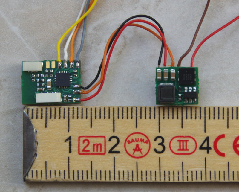
To connect:
- Connect the CTC-Loco-Module-XS3 and the CTC-Power-Module-XS: positive pole track voltage (VBB, orange), processor voltage (VCC, red) and negative pole (GND, black).
- Solder the buffer capacitor to the CTC-Power-Module-XS (rear side): positive pole track voltage (VBB, orange) and negative pole (GND, black).
- Solder the motor and lighting to the contacts shown in the image above: here an NEM-651 cable (motor grey and orange), lighting (front white, rear yellow).
- The solder pads on the top left in the image are the two additional LED connections (AUX).
- Plug the optional CTC IR receiver into the 6-pin socket on the CTC module.
The assignment of lighting and AUX connections to switches in the app can be freely configured (cfg.xml).
IR Receiver
We supply you with a cable with a suitable 6-pin plug for the IR receiver.
The socket on the module is a JST SM06B-XSRS-ETB. We also use this socket to flash the module via an FTDI cable. The pin assignment is as follows: 1-Reset, 2-Flash, 3-GND, 4-TX, 5-RX, 6-VCC.
PowerXS and Buffer Capacitor
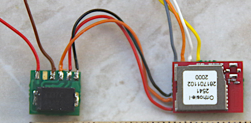
Connections on the Power-XS:
- The buffer capacitor is soldered to the voltage regulator PowerXS either directly as shown in the image or via a cable. The light (matt) bar on the capacitor marks the positive pole (VBB). For soldering, we use an orange cable for the positive pole (VBB) and black for the negative pole (GND).
- The track connection (red, brown) is soldered to the top left in the image (first and third solder pad).
- The three solder pads on the right are connected to the XS3 loco module: positive pole track voltage (VBB, orange), processor voltage (VCC, red) and negative pole (GND, black).
- The solder pad in the image between the track contacts is VBB and can be used as a positive pole for the loco lighting.