





The housing of the locomotive is hooked into the chassis all around with many lugs. To open it, I carefully bend the plastic housing outward and then slide business cards between the housing and the chassis so that the lugs do not snap back in. Once all the lugs have been levered out of their catches, the housing can simply be pulled upward.
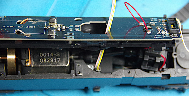
Since replacing the PluX22 decoder with a CTC-Loco-Module-PluX22 was easy, this time I started with the IR receiver. I removed the main circuit board and then drilled a hole for the cable in the chassis:
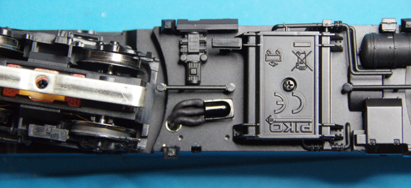
The IR receiver finds its place next to the bogie, where the wiper is mounted:
Then I replaced the DCC decoder with the CTC-Loco-Module-PluX22 and plugged the IR receiver into it.
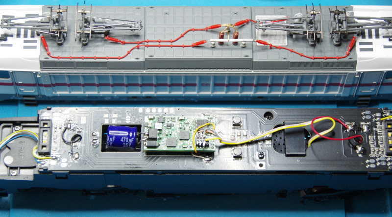
Initial test runs showed that the locomotive has no or only a much too small buffer memory. Although there is a capacitor connection on the main circuit board of the locomotive, it is not connected to the corresponding pins of the PluX22 socket. Therefore, I had to solder the backup capacitor to the solder points provided on the CTC-Loco-Module-PluX22. Unfortunately, the cutout in the main circuit board does not provide enough space for the 1000 uF capacitor usually used by CTC, but a 470 uF capacitor was sufficient:
Note: After this conversion, the Piko BR147 works so well that it has become the most frequently used locomotive during CTC development.