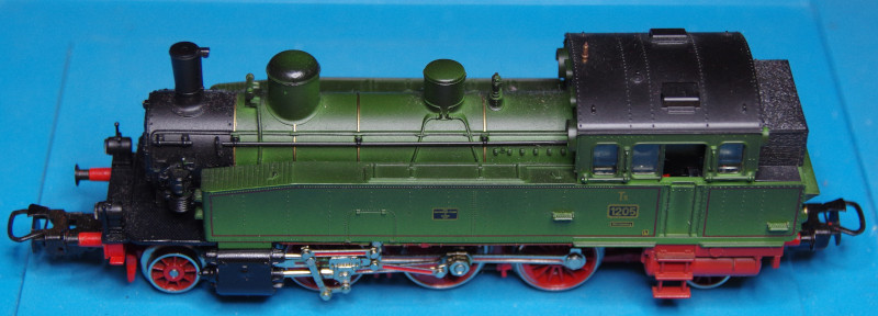
This time, it’s one of my childhood dreams: The Württemberg T5 from the set celebrating Märklin’s 125th anniversary. At that time it was unaffordable for me, but now I was able to get it cheaply on eBay.
Since we decided to stop producing the CTC-locomotive module-H0a, I will show here how to convert an analog model using the CTC-locomotive module-PluX22 and adapter board.
Upon opening, I got my first small surprise: In addition to the motor and switch, there was a previously unknown circuit board in the locomotive:
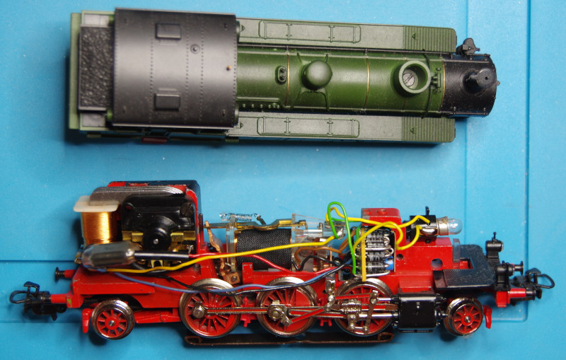
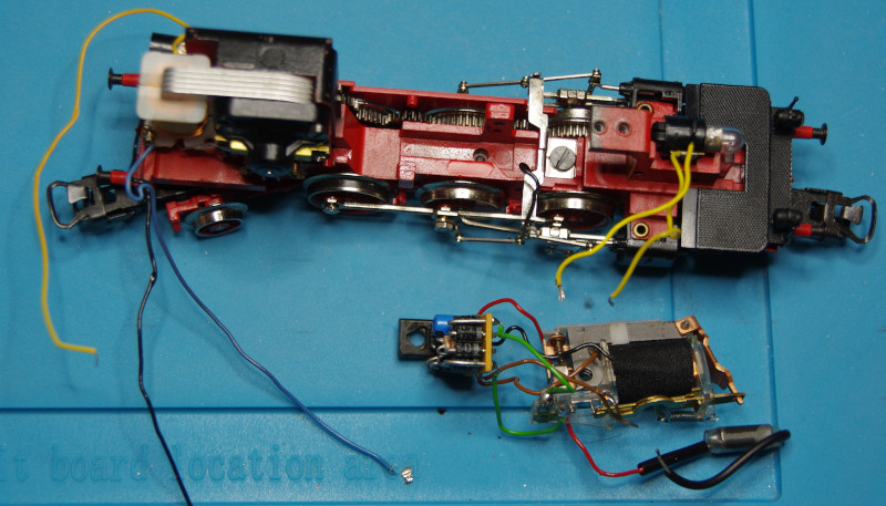
Presumably, this is designed to ensure consistently bright lighting since the bulbs are only rated for 1.5 volts, as I later discovered. In my various remodellings, however, I found it best not to try to understand the built-in electronics but simply to remove them:
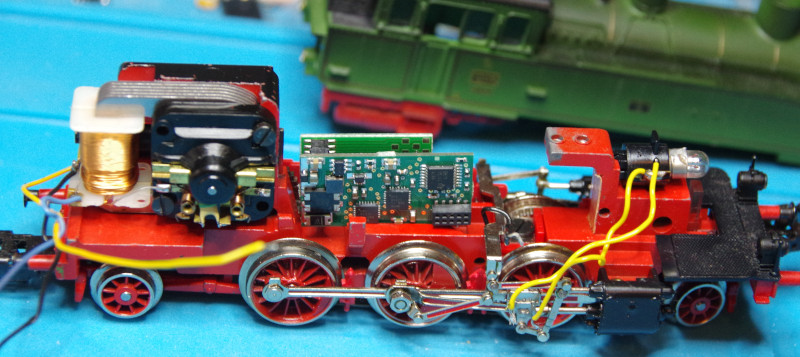
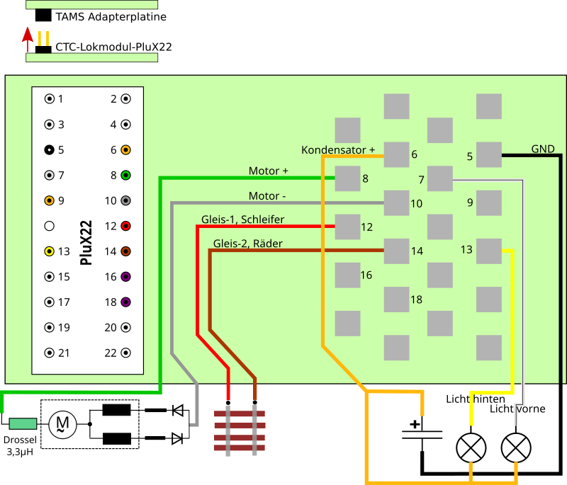
Before I start the installation, I first check how the CTC-locomotive module and adapter board fit best. This is particularly important as the TAMS adapter can be plugged in from the front or the back, which affects the pin configuration of the solder contacts. Here I have decided to plug it from the front:
This results in the following wiring diagram:
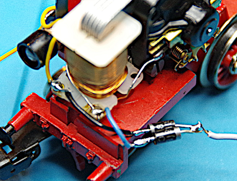
Then I start with the motor. First, a diode is connected to each of the two field coil terminals. It is essential to ensure that these are connected in opposite directions (see the gray rings). The other ends of the diodes are connected:
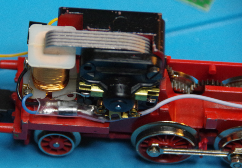
A gray wire is now soldered to the two diodes, which is connected to the “Motor-“ on the adapter. Then I pull a heat shrink tube over the diodes, long enough to cover all exposed wires and solder joints:
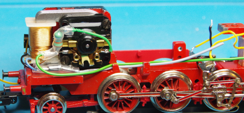
Next, I solder the choke to the second motor terminal and a green wire to the other end of the choke. The choke is also wrapped in a heat shrink tube:
The track connection is made via the black (original) cable from the pickup shoe (center of the image) and a soldering lug which I screw to the chassis at a suitable point. I used the spot where the old locomotive electronics were previously attached:
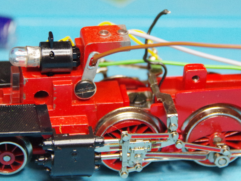
The bulbs in this case are connected with two wires, meaning we don’t need protection diodes. However, as they are only rated for 1.5 volts, we need to replace them with ones that can handle the full track voltage. In my research on the internet, I found suitable bulbs with LEDs for up to 22 volts.
For soldering the common positive of the bulbs, I use the positive leg of the support capacitor:
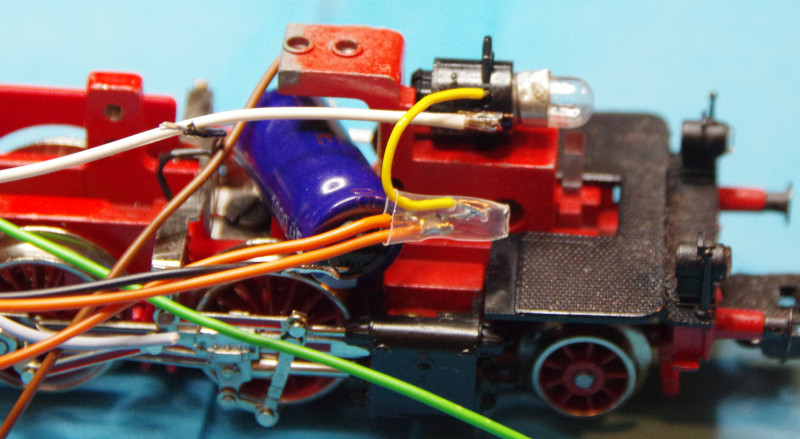
Here is a photo of the rear light:
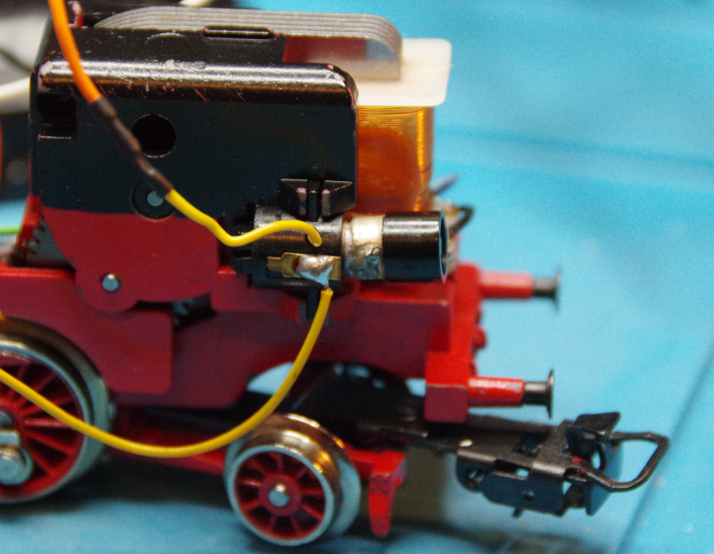
Since the solder pads are relatively small, it is worth considering in advance in which order I solder the wires to the adapter. Here is a photo of the completely wired locomotive:
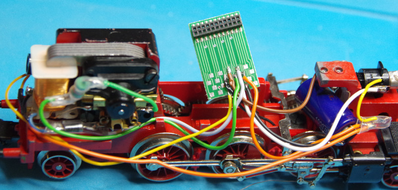
Only now do I plug the CTC-locomotive module (from the correct side!) into the adapter. Before I painstakingly stash everything away, I do a first functionality test on the rolling test stand:
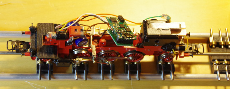
Then I slide a heat shrink tube around the locomotive module and adapter and carefully shrink it so that I can pull it off later:
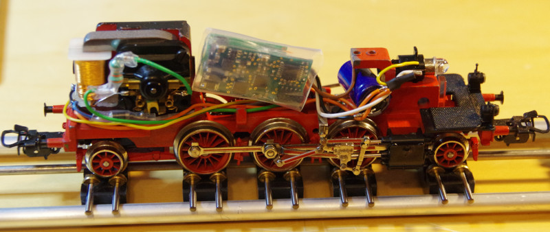
As so often happens, something else was more important, and the installation of the IR receiver had to be postponed. I will update this article as soon as the IR receiver is installed.


