The Bernina railcar is a current LGB model with a sound decoder.
For electric locomotives, I’m not particularly interested in the driving sounds, but occasionally blowing the whistle is nice. So, I decided to control the motor directly via the CTC-Lokmodul-G2 and use the original LGB decoder for the sounds. This leads to a previously unshown wiring variant: I use both motor outputs for the motors and connect the DCC decoder to two half-bridges.
With the old CTC-Lokmodul-G, there was a nasty surprise: The LGB-DCC decoder draws more than the 1-ampere limit of the half-bridge driver, at least during startup. This led to the decision to equip the CTC-Lokmodul-G2 with a more powerful driver of 2 amperes.
This is how the original electronics of the Bernina railcar looked after opening the housing:
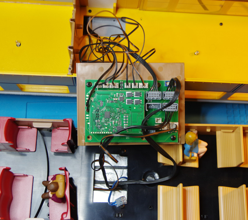
When designing the CTC-Lokmodul-G2, we also considered the cables with 4-pin connectors used in current LGB models: we optionally equip the connections for track and motor with appropriate pin headers (No. P2-05-08 or P2-05-09).
As always with LGB models, the 3.5 A version of the CTC-Lokmodul-G (No. P2-05-08) suffices. In the image, you can clearly see the two black cables with gray 4-pin connectors coming from the motor blocks, as well as the brown-red cable between the two half-bridges and the DCC decoder:
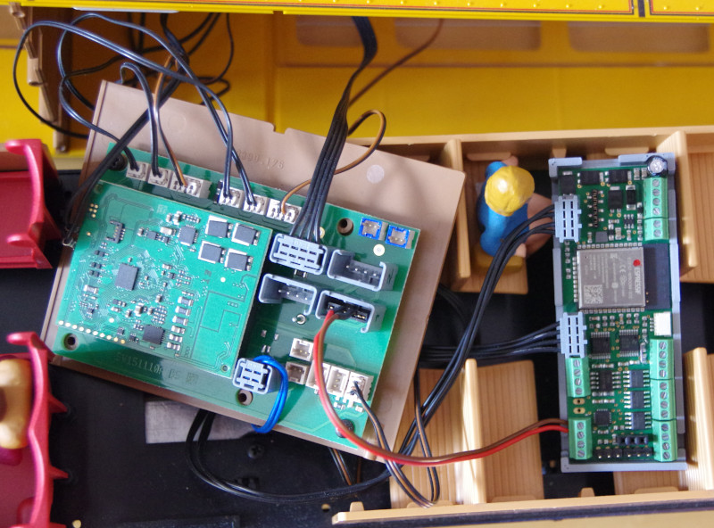
I saved myself the trouble of connecting the many lighting cables to the CTC module: the DCC decoder can switch on the lights just as well as the CTC module.
There is enough space in the Bernina railcar for the CTC module in addition to the original DCC decoder:
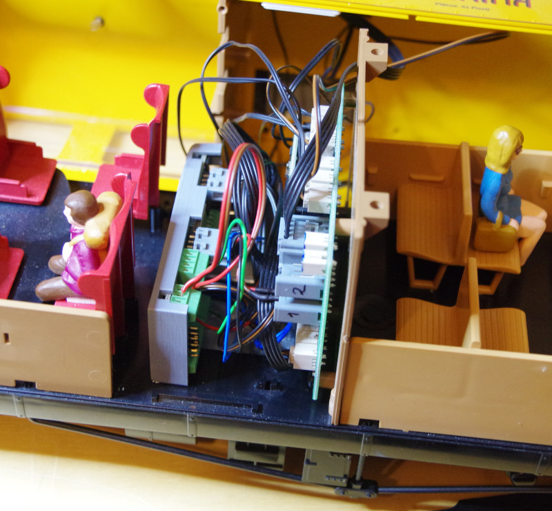
During reassembly, I was glad for the two helping hands of my wife.
Adjusting the Config
In the factory configuration of the CTC-Lokmodul-G2, the light is connected to the CTC module. Since this is not the case for me, I remove the light from the list of connected products with the minus button.
Then I select “Bridge-1” (HB-1 / HB-2) on the left and click on the plus button at “Pins, Ports, and Extensions” to add the DCC connection:
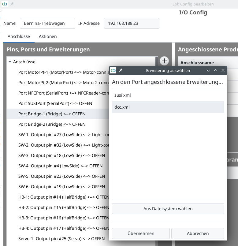
As usual with DCC, the standard address 3 is used.
I rename the “motor” added with the DCC extension to “DCC-Motor.”
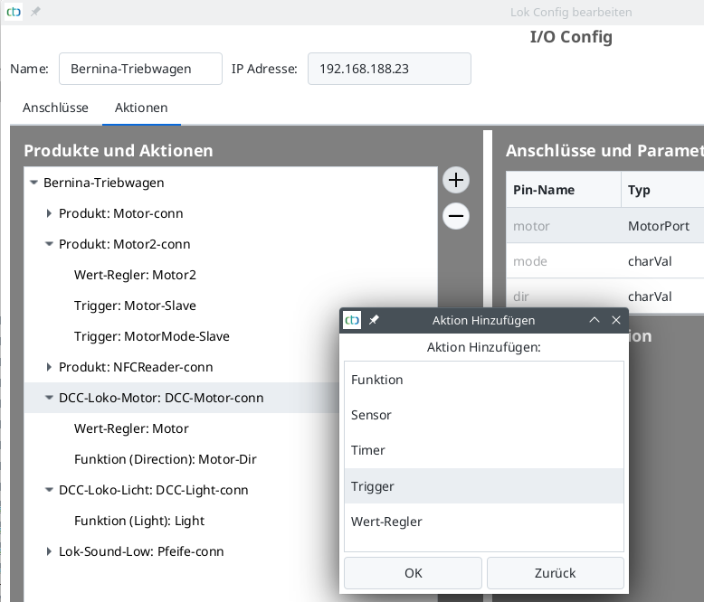
So that the headlight on the DCC decoder reacts to changes in the driving direction of the motor at the CTC module, I add a trigger at the DCC-Motor:
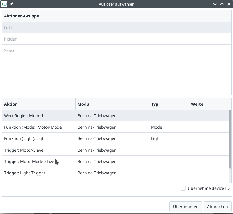
As a trigger for the trigger, I select the main motor (Motor-1):
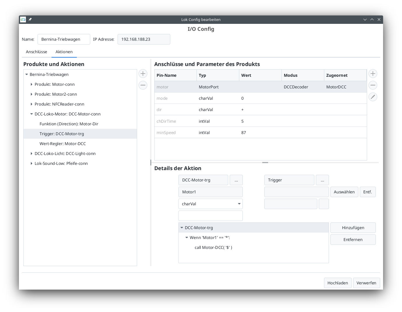
Then I supplement the trigger script so that the DCC motor takes over all state changes from Motor1. Unfortunately, the parameter value “$” (take the value from the trigger) cannot be selected in the CTC app (yet), meaning I had to select something else and then replace it in the HTML page with the character “$”. The finished trigger looks like this:
Finally, I added and linked the whistle (lok sound from “universell-loks.xml”) and the interior light (lok light from “universell-loks.xml”):
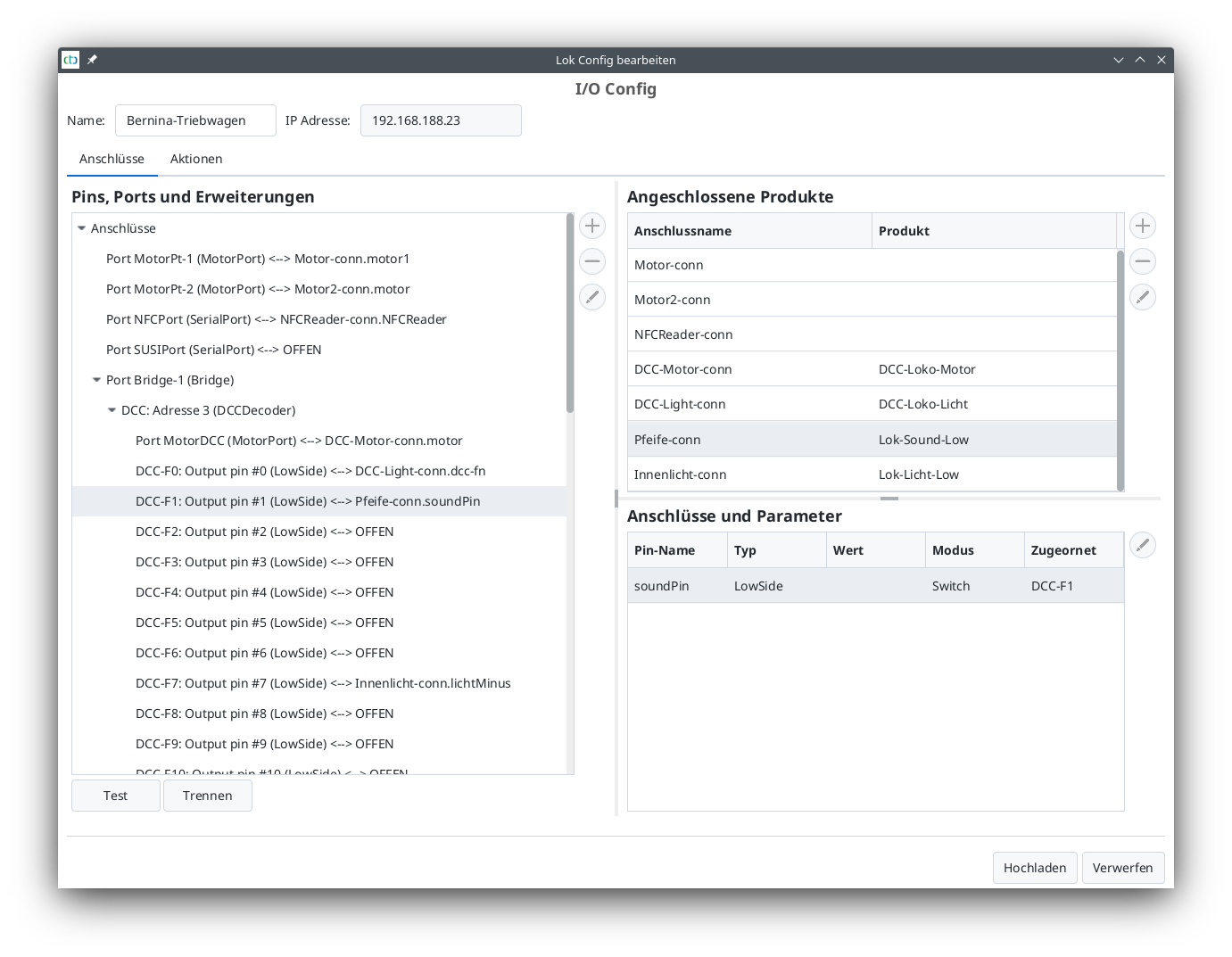
There could be many more sounds, but I’m content with just the one whistle.
I actually forgot to install the NFC reader - I need to catch up on that sometime.


