





The loco is opened via the screw next to the wiper, which is easily visible from below:
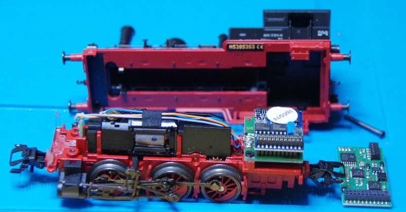
The socket looks like a 21mtc, but the specified space for the decoder is clearly too small. So I had to do some tinkering.
After downloading the exploded view from the Märklin website, it turns out that the cab can be removed and the cover plate above the decoder can be taken off. This significantly increases the space for the CTC module.
Unfortunately, even then there is no way to install the CTC module by plugging it onto the loco board. So I decided to remove the loco board entirely. Here is another picture of the wiring before I desoldered the wires from the loco board:
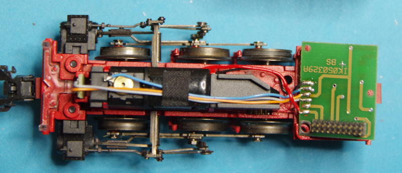
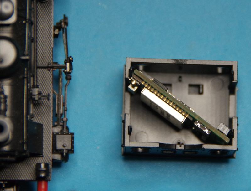
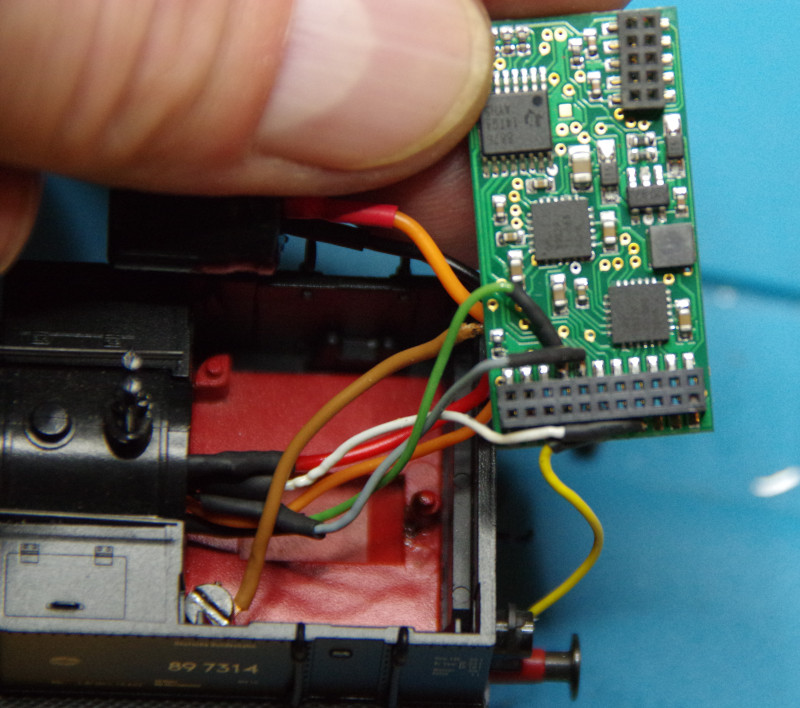
Even so, there is not enough space to connect the CTC-Loco-Module-21mtc via a plug. The CTC-Loco-Module-21mtc just barely fits diagonally into the cab:
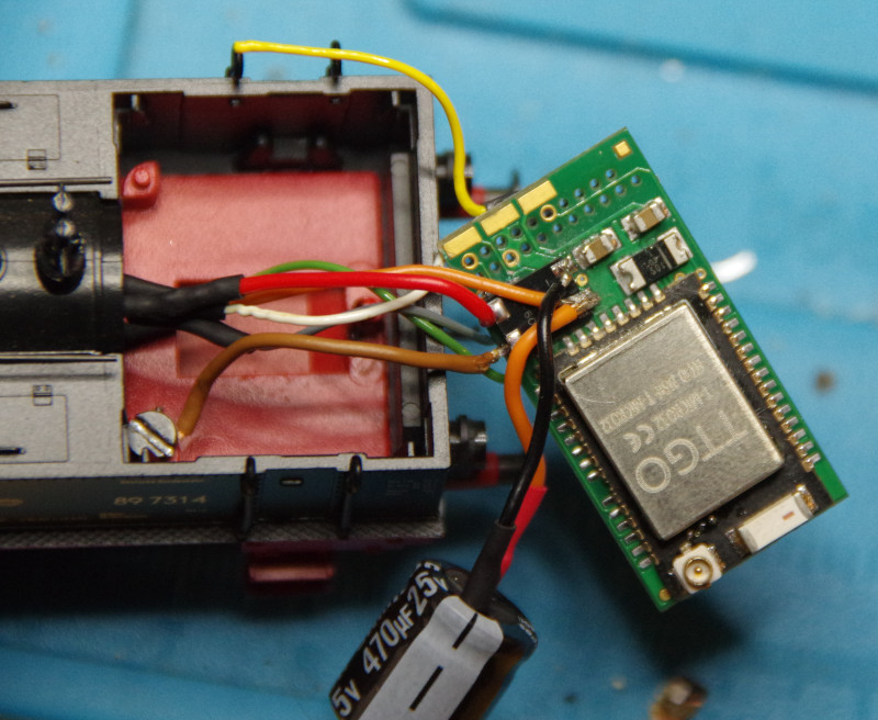
So I decided to solder appropriate wires to the CTC-Loco-Module-21mtc. The only remaining reason for using a CTC-Loco-Module-21mtc is that it is currently the smallest loco module from CTC. The wires for lighting, motor, and track are soldered on:
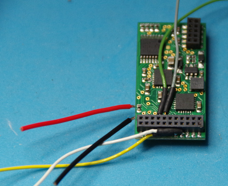
Soldering the track wires to the rectifier on this module was not a good idea: The rectifier was poorly positioned by the manufacturer, and soldering caused a short circuit under the rectifier. So I had to unsolder the rectifier and place a new one.
Then the voltage supply for the front LEDs and the support capacitor were still missing. After consulting with the customer, we decided to omit the rear light: it was implemented via LEDs on the loco board. Here is the finished soldered CTC-Loco-Module-21mtc:
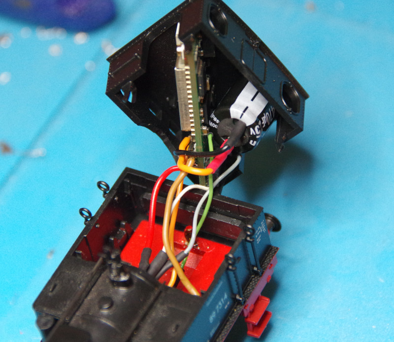
The loco module and capacitor (470 µF) fit inside the cab:
And this is what the assembled loco looks like:
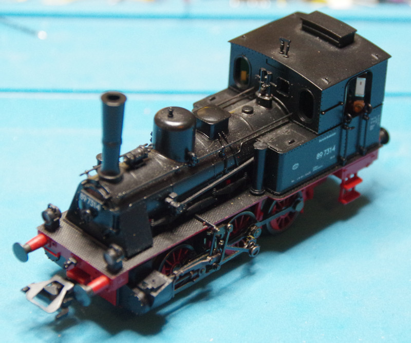
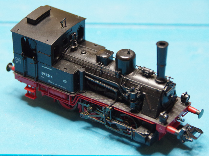
The white WiFi antenna sticking out of the window on the left could be hidden with black cardboard.