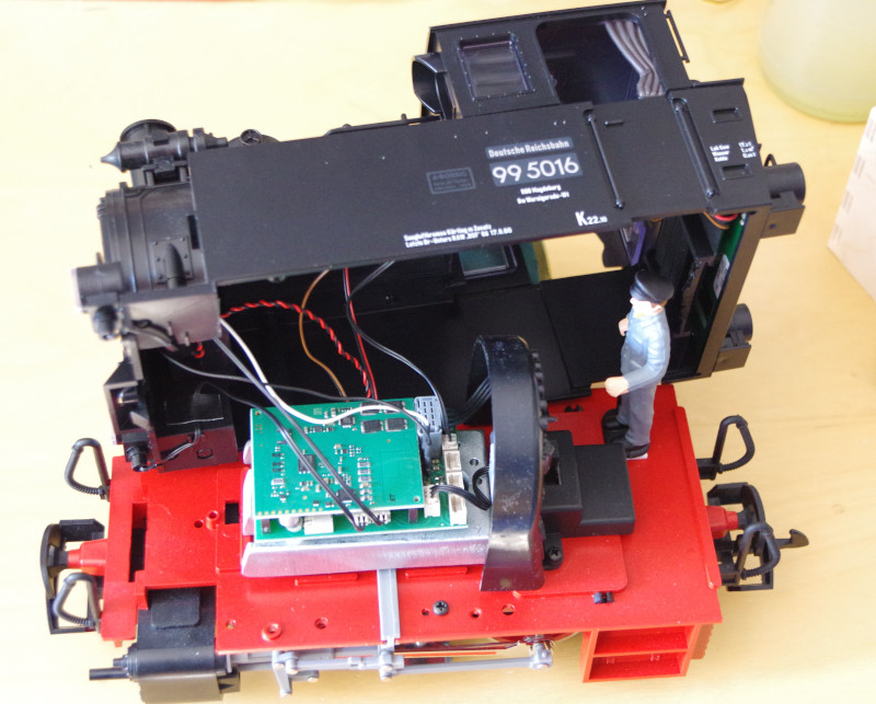
The locomotive is opened from below via two screws directly behind the cylinders. Then the typical LGB pins above the front buffer are pressed in and then the boiler and cab are lifted up. The housing then needs to be pushed back a bit to release the latch at the very back between the cab and the base plate. Be careful when lifting the housing, as it is connected to the base plate by several cables:
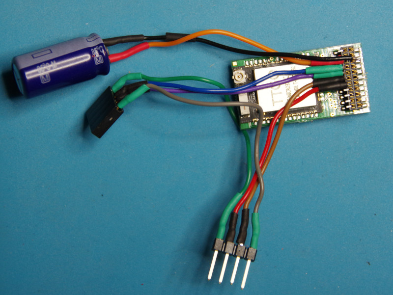
Due to the tight space in the locomotive, I decided on a CTC-Lokmodul-PluX22 instead of the CTC-Lokmodul-G. Since I wanted to keep the original sound, I decided to install the CTC-Lokmodul-PluX22 between the track and the original DCC decoder.
It would have been easier with commercially available adapter boards. But since I didn’t have any on hand, I inserted an SMD socket and then soldered the cables there. A 2.54 mm pin header and corresponding socket allow me to install the CTC module between the track and DCC decoder. A support capacitor should never be missing.
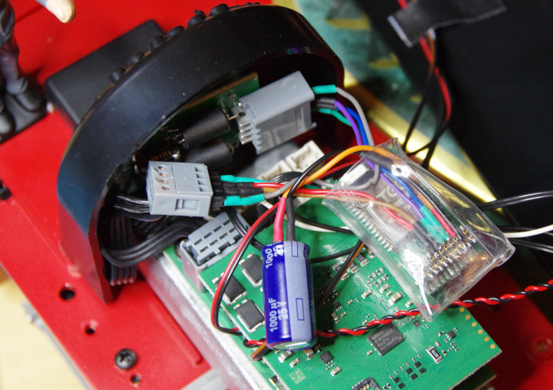
The gray socket in the top left of the picture was plugged into the connector on the board in the top right. I pulled it out and plugged in the prepared pin header there. Accordingly, I plugged the socket into the connector on the board:
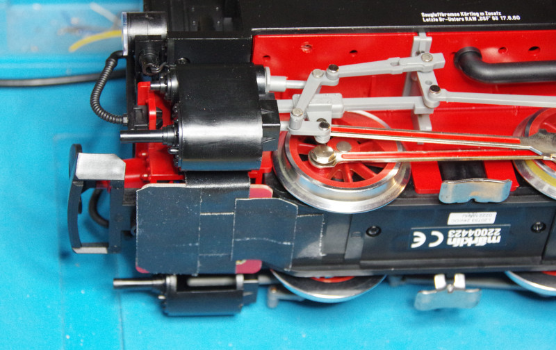
Next, the NFC reader is connected. I placed it in the front between the cylinders. For the cables, I drilled a 3 mm hole, threaded the cables through, and then soldered them to the mini plug.
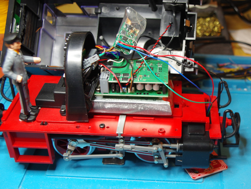
The following picture shows the mini plug for the NFC reader more clearly:
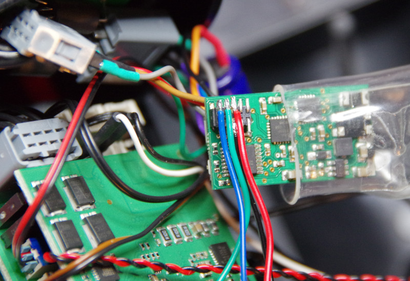
I fixed the NFC reader with fabric tape. Maybe there will be a nice 3D-printed holder at some point, but for now, the fabric tape is sufficient.
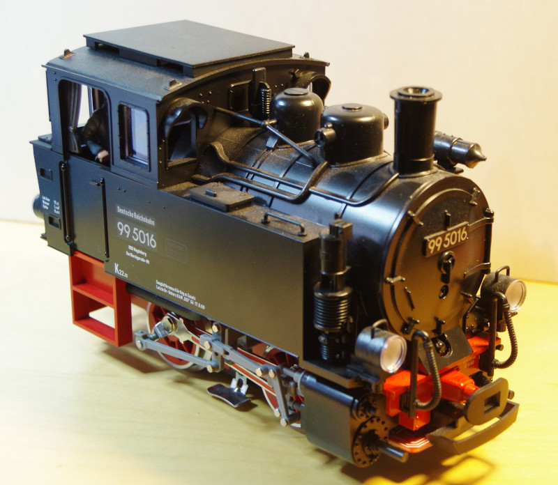
This is what the finished locomotive looks like. The NFC reader is hardly noticeable:
Now, let’s move on to the configuration. I registered the locomotive on the WLAN and then opened the configuration:
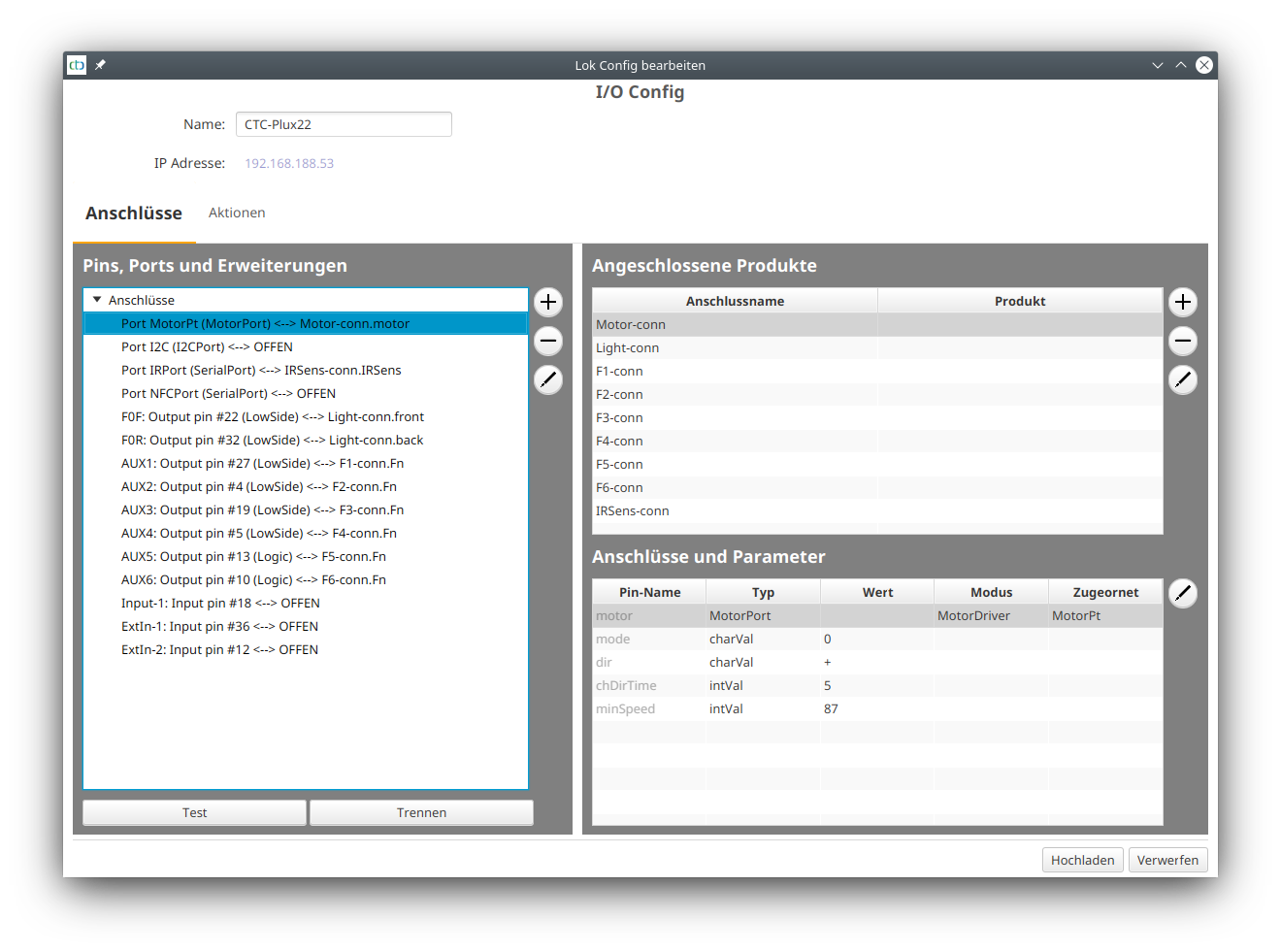
Since all functions are connected to the DCC decoder, I removed them from the CTC configuration for now:
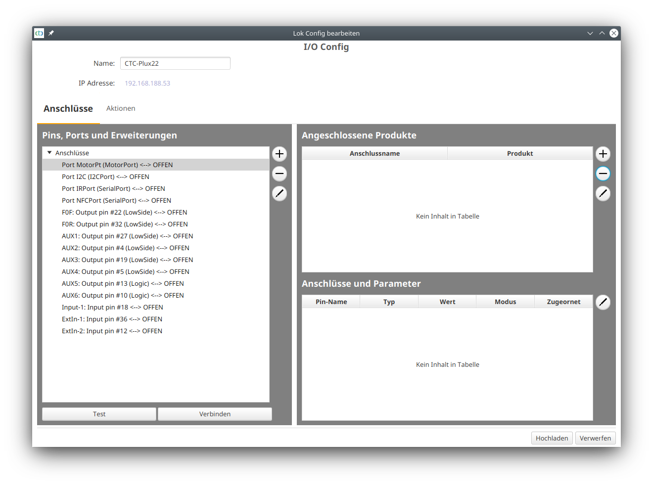
Then I mark the motor connection (“Port MotorPt”) and click on the plus button to the right of “Pins, Port and Extensions”:
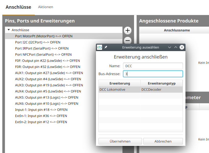
I name the extension “DCC” and enter the DCC address of the locomotive at Bus Address. Since I never operated it with a digital central unit, it still has the DCC default value 3. Then I click on “Apply”:
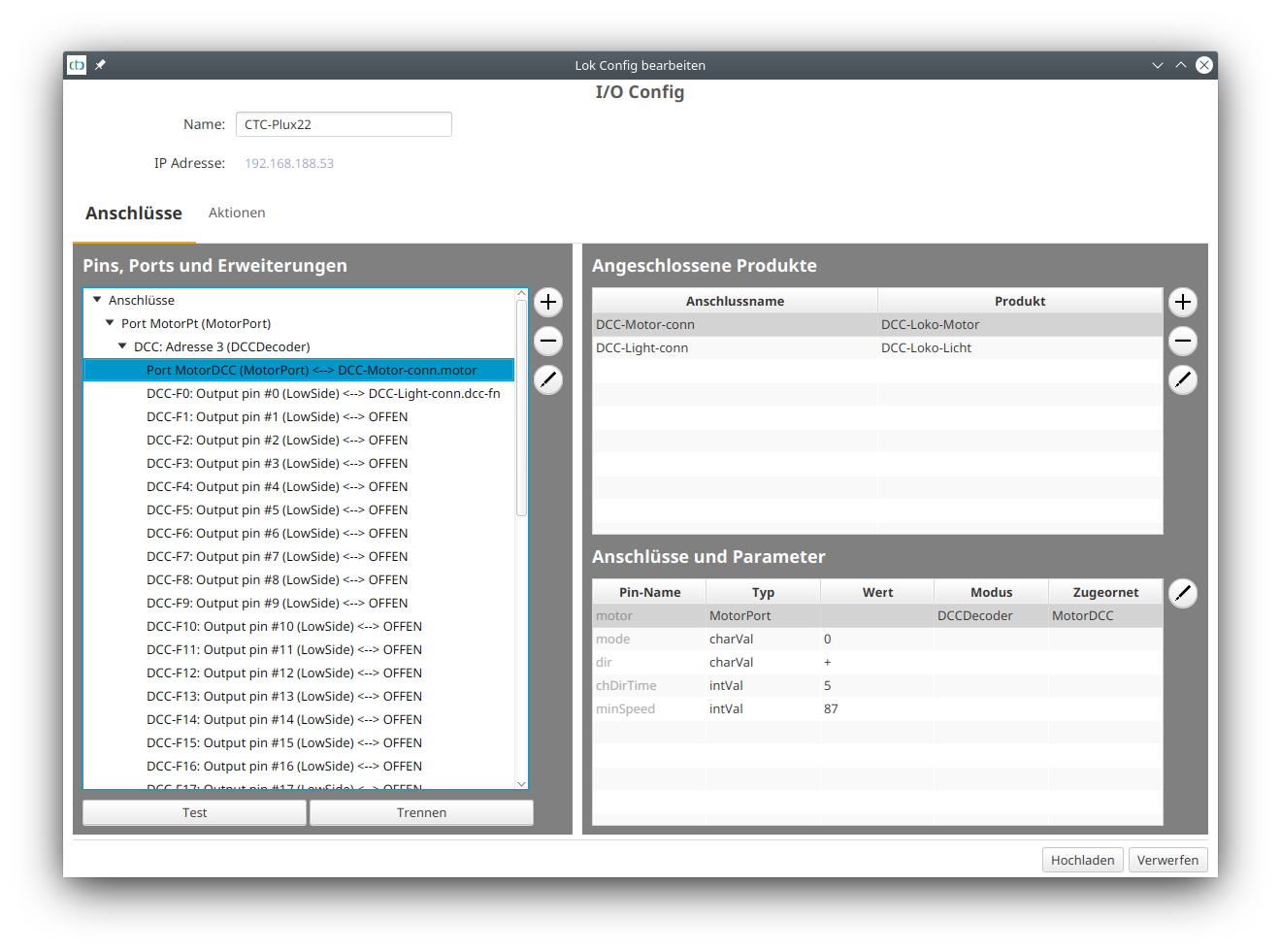
Next, I set up the sounds and link them with the DCC functions according to the DCC decoder documentation. To do this, I click on the plus button next to “Connected Products”:
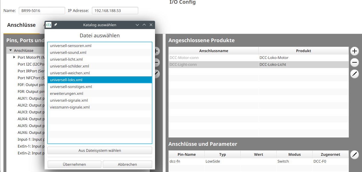
Then I select “universell-loks.xml”:
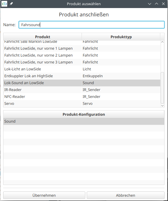
I give the sound a name (here “Driving Sound”), select “Lok-Sound an LowSide” and click “Apply”:
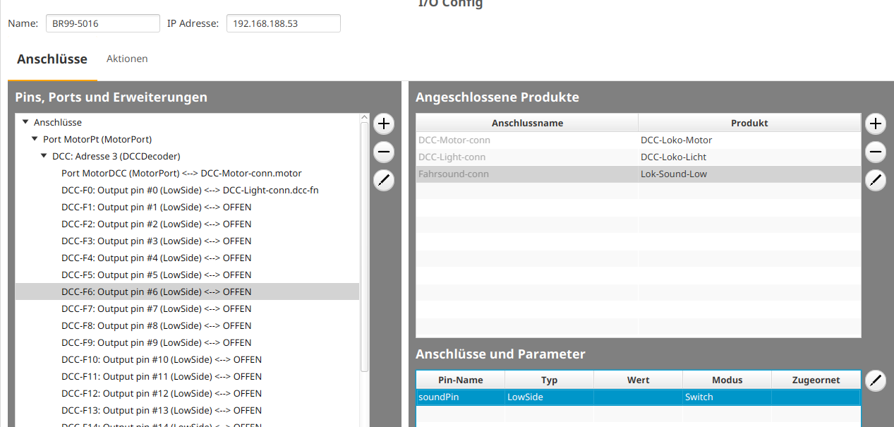
Then I select the appropriate function (here DCC-F6), mark the “soundPin” at the bottom right, and click “Connect”.
To configure the NFC reader, I click on the plus button next to “Connected Products” again:
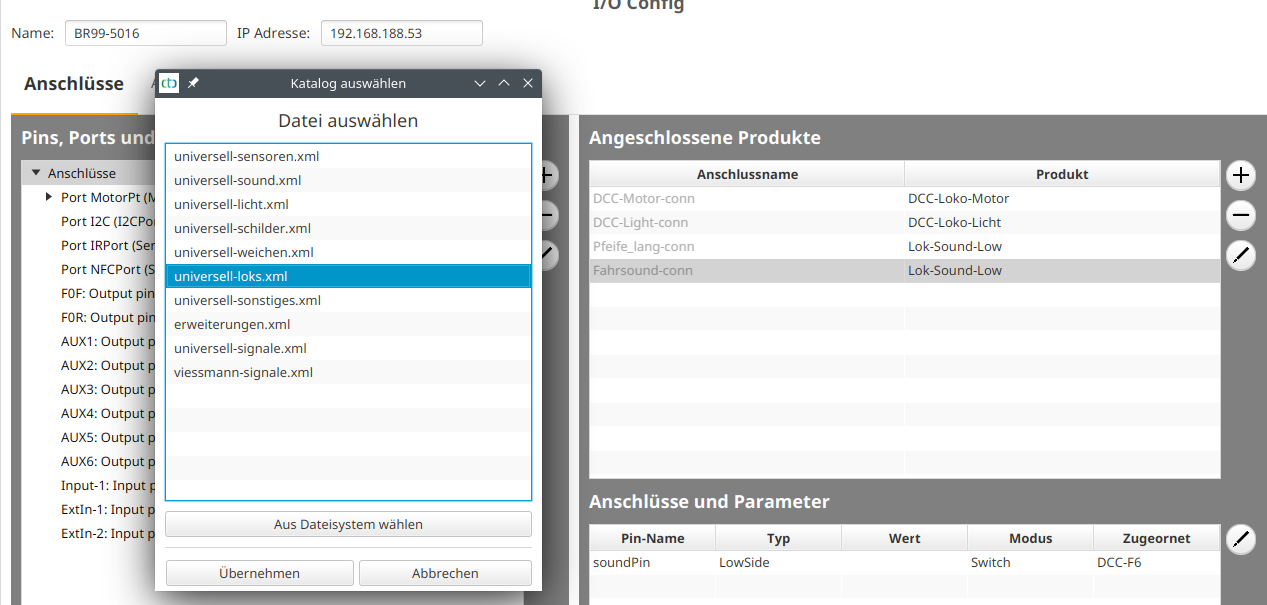
I select “universell-loks.xml” again:
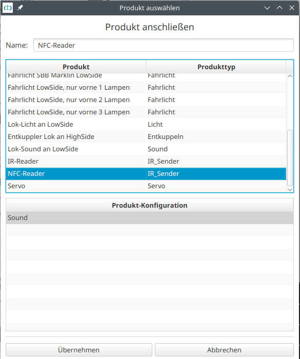
I give the NFC reader a name, select “NFC-Reader”, and click “Apply”. Then I connect the NFC reader to the “Port NFCPort”:
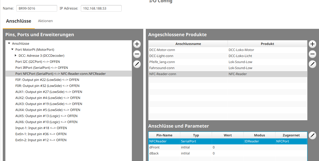
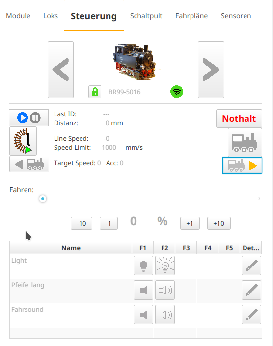
This is how the BR99.5016 appears in the “Control” tab of the CTC app:
