Under the name “Sinus drive,” Märklin installed brushless motors in some of its locomotives for a while. These motors require a special control that CTC locomotive modules do not currently offer. rail4you.ch has filled this gap with the driver-electronics “DsM-2.0”. This driver can be connected to a bridge output of a CTC locomotive module.
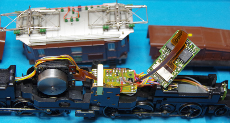
Here, we see the original electronics. This also consisted of a special decoder (removed, on the right in the image) and an auxiliary circuit board (between the motor and decoder). The 8-wire flat cable between the motor and decoder is also clearly visible:
The following image shows the parts needed for the conversion to CTC:
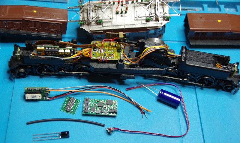
In front of the locomotive:
- Sinus driver from rail4you (top left)
- 21-mtc adapter board from eBay (right next to Sinus driver)
- CTC locomotive module 21mtc (center)
- Buffer capacitor 1000 uF (top right)
- IR receiver diode and shrink tubing (bottom left)
- Cable for IR receiver with a 10-pin mini connector
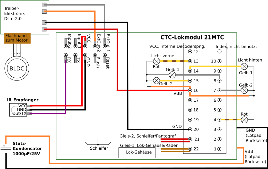
The wiring of power supply and lighting is done as usual for locomotives with Swiss light change. Only the motor connection is unusual. Here is the complete circuit diagram:
Soldered to the 21mtc adapter:
- the 2 cables from the locomotive chassis/wheels (brown) and from the slider/pantograph (center conductor, red) to Track1 and Track2 - the orientation does not matter.
- the 6 cables of the front and rear lights (each yellow, brown/yellow, and gray) to the F0f, F0r, F1, F2, F3, and F4 connections on the 21mtc adapter. No specific assignment needs to be maintained here, as we will test and assign the connections later during configuration.
- the common positive pole of the lighting (orange) is connected to VBB (decoder plus).
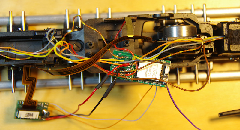
For the Sinus driver, solder:
- the 2 power supply cables: red to V+ (labeled as VBB on the CTC module) and black to GND (see image above)
- the 2 cables for picking up the motor signals from the CTC locomotive module 21mtc to the 10-pin mini connector to which the cables for the IR receiver are already soldered. The white cable was soldered to “ExtOut-1 (Pin 25)” and the yellow cable to “ExtOut-2 (Pin 21)”.
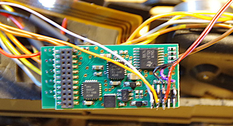
The flat ribbon cable from the Sinus motor is inserted into the corresponding slot of the Sinus driver (contacts facing the board) and then locked:
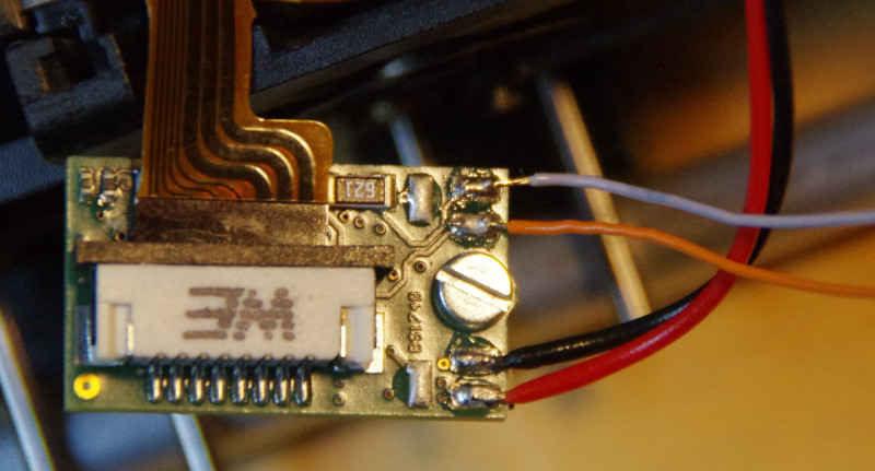
The Sinus driver is mounted in the locomotive housing (on the left in the image) with the supplied screw. The CTC locomotive module 21mtc is isolated with shrink tubing and then placed together with the capacitor in the center of the locomotive:
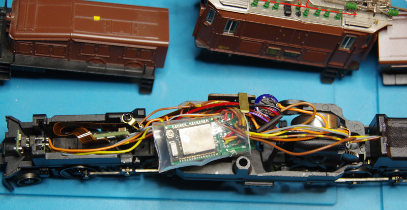
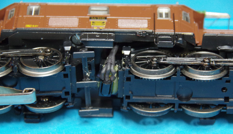
The IR transmitter found a suitable place in the middle under the locomotive on the motor block:
To configure the lights, the pre-installed lights are removed and then “SBB LowSide driving light, 2x yellow and 1x red each” from the product catalog “universal locomotives” is added:
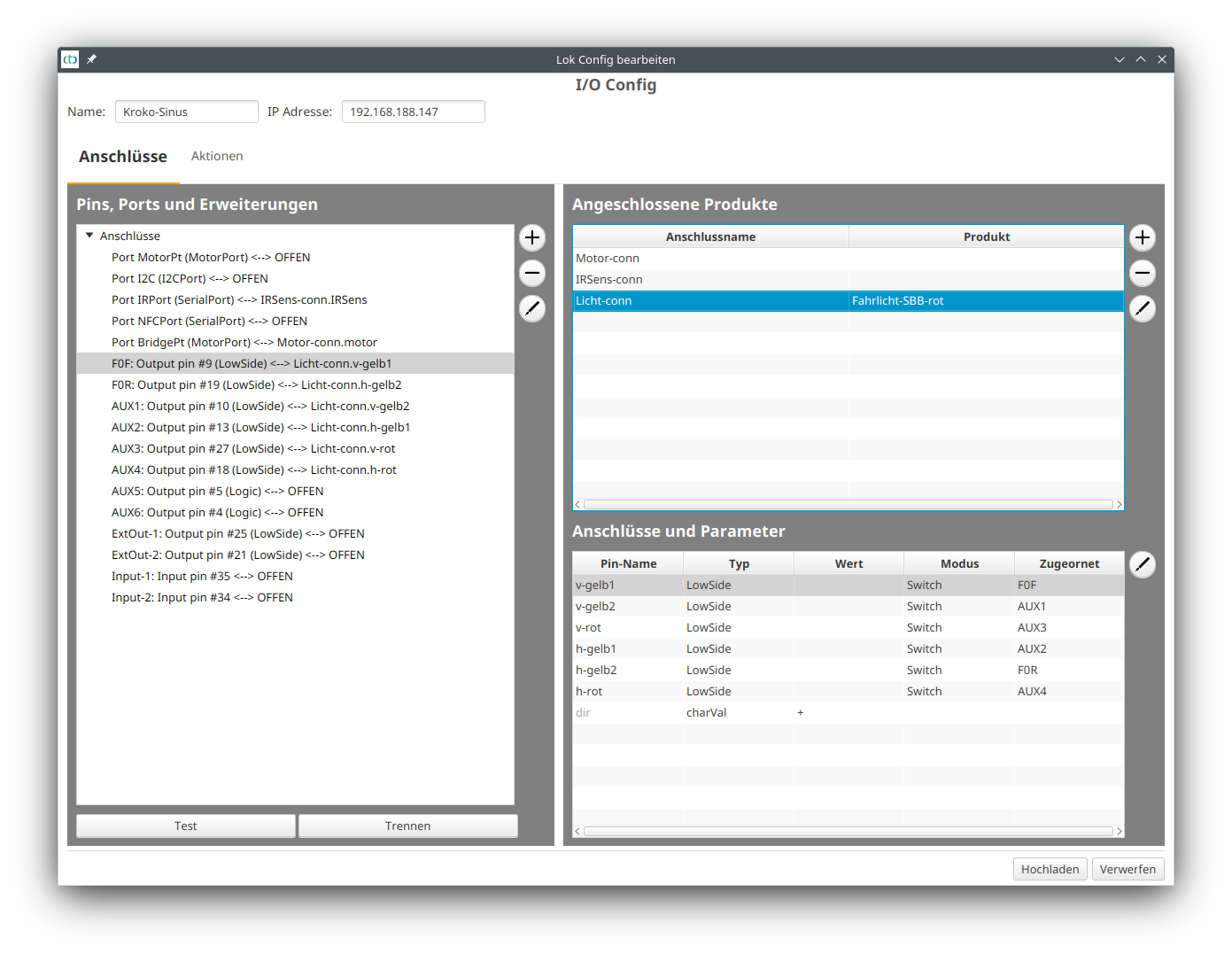
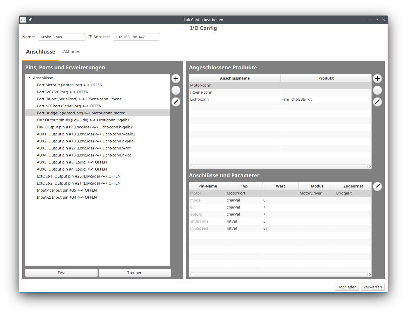
An up-to-date IO configuration (at least CTC App 4.19) is needed for the motor. For older CTC locomotive modules, this can be replaced by updating the firmware using the new “Replace IO Config” button (see Chapter 4 - “Configuring Modules”).
Then the motor can be disconnected from “MotorPt” and connected to “BridgePt”:
