





This document is dedicated to the infrastructure that you only need to set up once for a model railway system. For CTC, this includes the power supply and the WiFi router.
Power Supply
Caution: An unsuitable power supply can irreparably destroy the CTC modules
For a model railway operated exclusively with CTC modules, we recommend purchasing a short-circuit-proof switched-mode power supply for direct current. At Reichelt, you can find the following recommended desktop power supplies:
If you prefer more flexibility, you can also use a laboratory power supply, e.g., PeakTech 6226 . These have the advantage of an integrated display for voltage and current, but also the following disadvantages:
- You can accidentally adjust the voltage and then destroy all CTC modules at once when you switch it on next time.
- A laboratory power supply typically does not switch off in the event of a short circuit but only limits the current to a settable value.
If you plan to operate a mixed system with analog or older digital components, you need to consider the following:
- The CTC modules are not suitable for alternating current (AC) or unfiltered direct current (DC) in their default state. Old model railway transformers often supply unfiltered direct current.
- CTC modules can be operated without concern on so-called digital current (alternating current at approx. 10 kHz).
- If you use a separate power supply for your CTC modules, ensure that there are no cross-connections between the CTC module and track power. A classic example is the old Märklin turnout, where a cross-connection exists between the track and turnout motor via the turnout lantern. With alternating current on the track, the CTC module will be destroyed without a protective diode across the bulb.
Power Requirements
When selecting a new power supply, the question also arises of how much current it must provide. Here are a few points of reference:
- The current requirement of the CTC modules can be found in their respective data sheets.
- Add the current requirement of the locomotives running simultaneously.
- When the lighting is switched on, especially old-fashioned incandescent bulbs play an important role.
- Turnout motors require a lot of current, but only while they are switching. In this case, the inrush current is most relevant, as CTC modules typically set turnouts to their default position at the beginning.
The easiest way to arrive at a reasonable value is to measure the current, especially the inrush current, and round up the measured value (very) generously.
To reduce the inrush current, you have the following options:
- Set a value in the config as the default for your turnouts that does not exist. However, the turnout will then be in an undefined state from the perspective of the CTC app.
- In addition to the previous point, you can use triggers or a button to initialize the turnouts one after another. We will certainly write an article on this topic at some point. Until then, feel free to contact us if needed.
Alternating Current and Unfiltered Direct Current
It is basically possible to use CTC modules with alternating current and unfiltered direct current. However, protective measures must be taken before commissioning:
- All CTC modules must have a suitable smoothing capacitor for the input voltage. Current turnout modules and I/O boards are already equipped with such a smoothing capacitor.
- There must be no unprotected cross-connections between the CTC module and track power (see below)
- Old transformers tend to react with violent overvoltages in the event of short circuits. See the section "Overvoltage Protection" below.
Protecting Against Cross-Connections
Here are some examples of cross-connections and how they can be protected:
- Old Märklin turnout (M-track): Install a protective diode between the bulb of the turnout lantern and the turnout motor.
- Old Märklin locomotives where one pole of the lighting is permanently connected to the housing: Install a protective diode between the bulbs of the front/rear lighting and the connection to the CTC-Loco-Module-H0a.
Overvoltage Protection
All power outputs (motor, switching outputs, half-bridges) of the CTC modules are protected against short circuits and overload, but the input must not exceed the maximum voltage of 24 volts. With transformers without electronic regulation, a short circuit can cause a high induced voltage at the track input of the CTC modules, which can damage or destroy them. This risk is particularly high when using old transformers.
Even a switched-mode power supply attempts to compensate for a current increase, such as that caused by a short circuit. While regulation overshoots cannot be prevented, they should be so brief that the connected electronics are not damaged. However, there are hardly any power supplies designed specifically for garden railways, let alone for CTC. Therefore, even when using a modern switched-mode power supply for CTC modules, fatal overvoltages can occur.
The interaction of the rest of the electrical/electronic components installed in the model railway can also amplify overvoltages or trick the regulation of a switched-mode power supply. Many unfavorable factors combined can be just the tipping point for CTC modules or other electronics.
Since this knowledge is based on specific customer experiences, we have looked for a protective solution. TVS diodes are the electronic components for this purpose, e.g., the SA24CA from Littlefuse . From February 2025, we will include such a TVS diode with all CTC-Turnout-Modules and CTC-Loco-Modules for N scale. For small scales, it should be sufficient to install TVS diodes in the track. For CTC modules already delivered, we will include the TVS diodes with the next order.
The dimensioning of the diodes is a compromise between size and protection. Whether they can withstand the voltage surge of a transformer must be shown in practice - we cannot guarantee this. Therefore, we can only recommend replacing the old transformer with a modern electronically regulated power supply to prevent overvoltages in the event of short circuits.
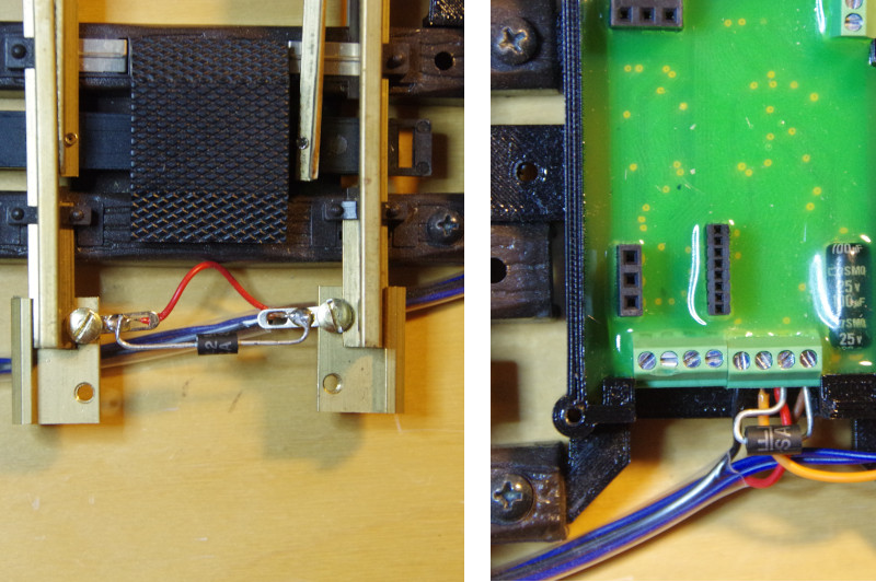
The TVS diode is simply placed between the two track connections (Track-A and Track-B). Since it is polarity-safe, nothing can go wrong. Installation in the power supply to the track or simply at any point in the track is also possible. If TVS diodes are installed at multiple points on the layout, they protect the CTC modules in the event of a short circuit. They also prevent electrostatic charging (ESD).
Here are two examples of installing a TVS diode, one in the track and one at the track input of the CTC-Turnout-Module-G2:
WiFi Router
Basically, anything that supports 2.4 GHz and WPA2 encryption should work. The CTC modules and the CTC app must be able to communicate with each other unrestricted via UDP and HTTP. If the router also supports 5 GHz, this frequency can be used for tablets, smartphones, and PCs, further increasing reliability as all data packets must pass through the router. Based on good experiences and wide availability, we have chosen the FRITZ ox 4040 as the CTC-Router .
If you order a CTC router, whether in a starter set or separately, you will receive it fully configured. Since we then know the network name (SSID) and network identifier (password), we will pre-register your CTC modules for your model railway WiFi when we ship them to you. This service is the reason for the price premium of the CTC router compared to a standard FRITZ ox.
In principle, there is nothing to prevent you from configuring your model railway WiFi yourself. Registering the CTC modules is very simple, as you can read in Chapter 3 - Registering modules in the WiFi . However, configuring the WiFi can be quite a challenge.
If you are unsure about this, we recommend the CTC router or the starter set.
Please understand that we can usually provide little or no assistance with the installation of unknown routers.