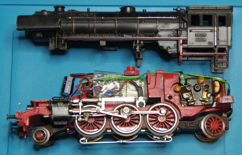
The steam locomotive is opened via the easily recognizable screw in the dome in front of the cabin:
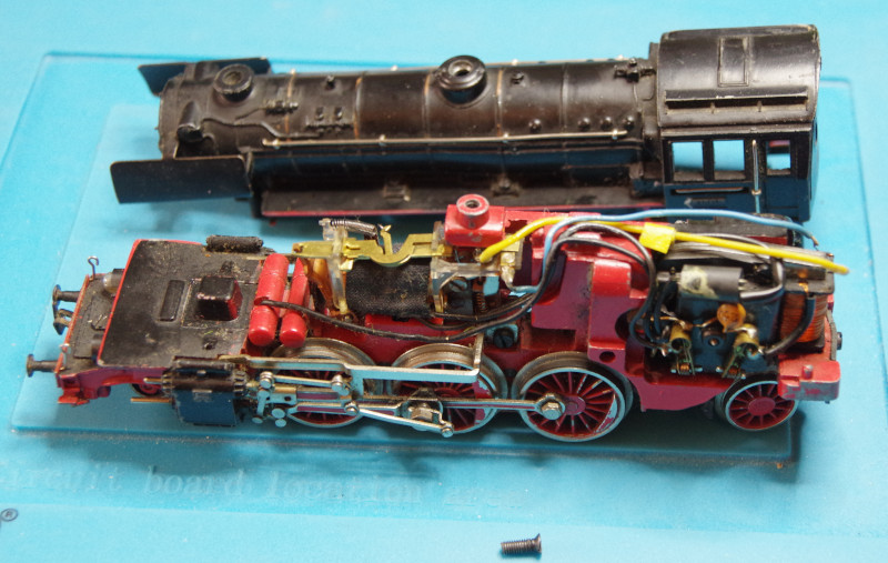
The locomotive presents itself as a classic analog Märklin locomotive with a universal current motor. A detailed guide for locomotives of this type can be found in the article Conversion E103 Märklin 3054.
The wires are removed from the guides. The photo documents the condition before beginning to unsolder wires. The light blue and yellow cables of the motor have already been unsoldered:
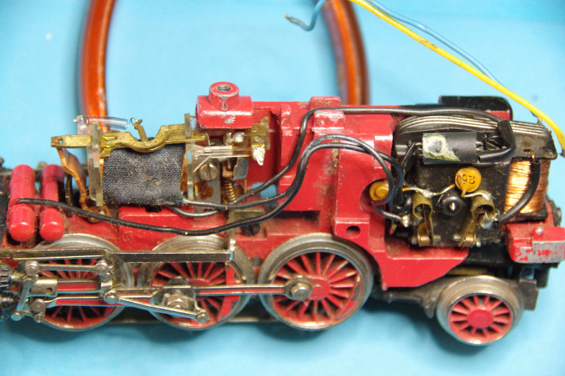
Here you can see the old wiring of the motor in detail:
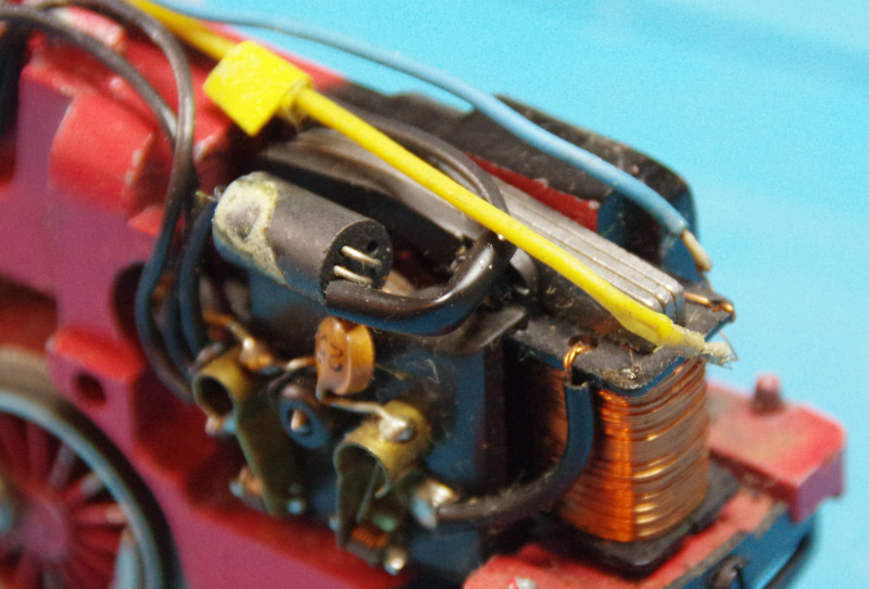
Now the reverser is removed. The old radio interference suppressor is also no longer needed.
In the following image, you can see where the CTC module is to be placed.
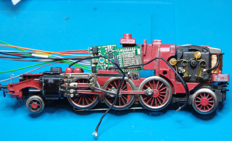
The wiring diagram below shows the connections of the CTC locomotive module with the individual components:
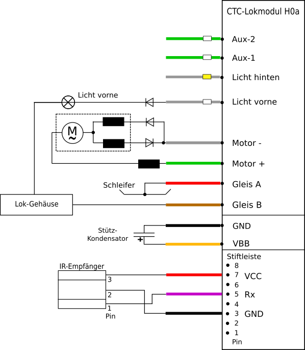
Since the CTC module cannot be directly screwed to the locomotive and thus does not have an electrical connection with the housing, the brown cable of the CTC module (Track B) must be connected to the housing via a soldering tab.
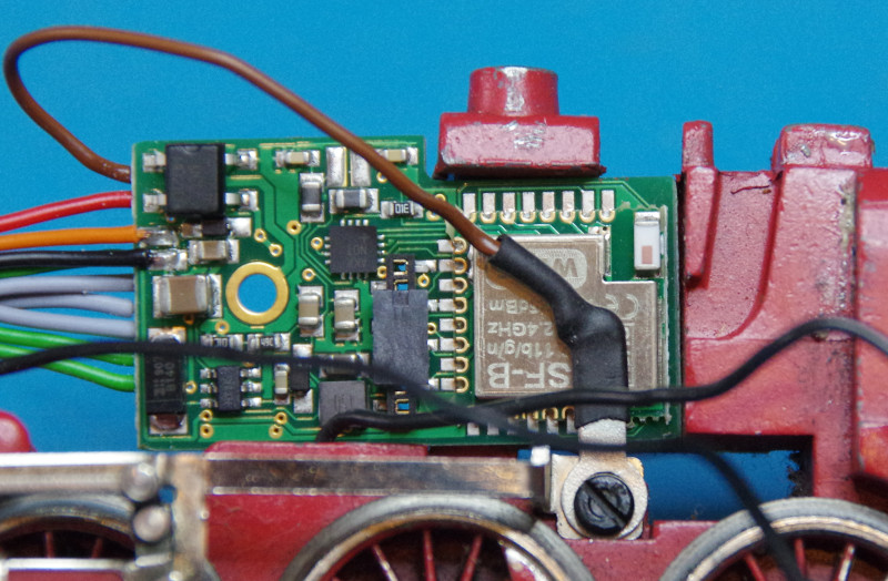
From the accessories for the locomotive conversion H0a (CTC-No. P2-12-01), the ferrite choke (3.3 µH) is soldered to the open motor pole. The other end of the choke is later connected to the + motor output of the CTC module.
The field coil is still connected to the other motor pole. At its connections, which were previously connected to the reverser, two diodes are connected in different conducting directions. The other ends of the two diodes are joined together and later connected to the - motor output of the CTC module.
Since the front lamp is connected to the locomotive housing, a diode must be installed between the lamp and the “front light” output on the CTC module in any case.
Now the cables of the CTC module are soldered to the motor, the light, and the buffer capacitor.
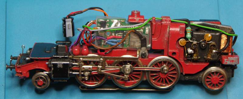
In the following image, the CTC module and the buffer capacitor are installed. Motor (green and gray cables) and light (gray cable) are connected:
Now the IR receiver is still missing. In the BR23, it is recommended to fix it to the suspension of the front wheel. The cable is loosely placed around the fastening screw to ensure the necessary flexibility:
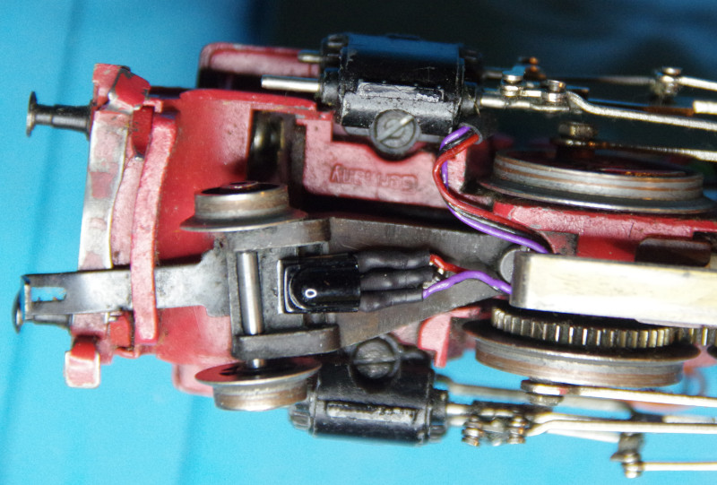
Here you can see the IR receiver fully installed. The connections of the IR receiver are covered with a heat shrink tube for electrical insulation. The cable of the IR receiver is routed behind the linkage in a black heat shrink tube upwards:
Finally, the housing of the steam locomotive is carefully reattached to the chassis. Care should be taken that no cable gets pinched:
Afterwards, the converted locomotive is tested on a track layout.
If necessary, the correct travel direction may still need to be set in the software.


