Notes:
- This conversion is still based on the old CTC-Lokmodul-21mtc. With the new CTC-Lokmodul-M3, it is much easier—see the conversion BR 247 M3-SUSI.
- The first part of this documentation dates from 18.08.2020 and was supplemented on 04.09.2023 with the chapter “Adding SUSI3 Sound.”
The locomotive’s housing is secured with four screws accessible from below (under the bogies).
Since replacing the 21mtc decoder with a CTC-Lokmodul-21mtc is straightforward, I will start here with the IR receiver.
The IR receiver is placed next to the bogie without a pickup: With this locomotive, the bogie has enough play, so I don’t need to drill a hole in the housing for the IR receiver cables:
Next, the 21mtc decoder is replaced with the CTC-Lokmodul-PluX22, and the IR receiver is plugged into it.
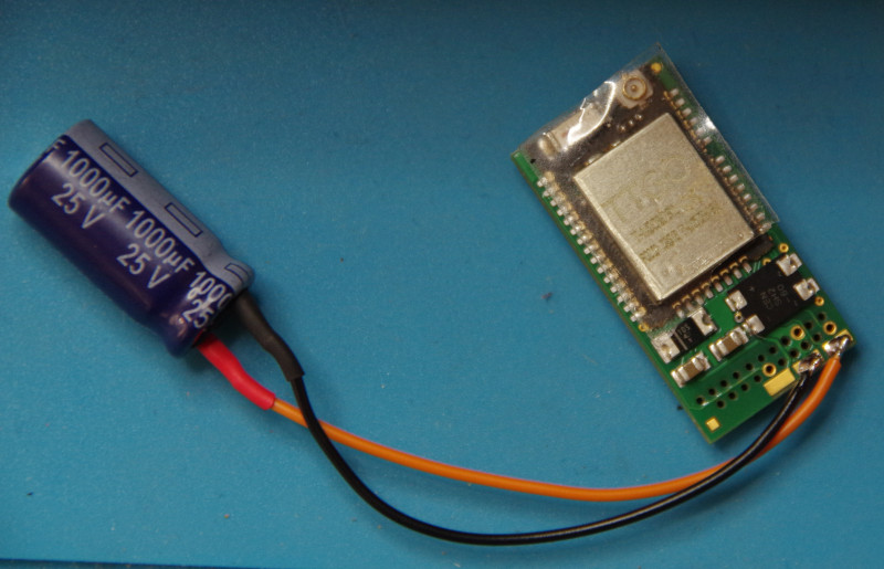
Initial test runs show that the locomotive either has no buffer capacitor or one that is far too small. Since the locomotive’s circuit board (unfortunately typical for Märklin) is undocumented, I refrain from searching for a connection point for the buffer capacitor there. Instead, a 1000 µF capacitor is soldered to the designated pads on the CTC-Lokmodul-21mtc:
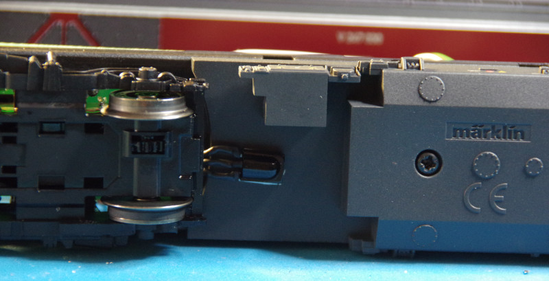
This is how the fully converted locomotive looks. If I hadn’t wanted to install the IR receiver, simply removing the roof would have been enough to replace the decoder with the CTC-Lokmodul-21mtc:
Adding SUSI3 Sound
The BR247 locomotive was originally equipped with a 21MTC sound decoder. We replaced this with a CTC-Lokmodul-21mtc, which initially meant losing the sound functionality. Starting with firmware 20230902 (delivered with CTC-App 4.19), the CTC-Lokmodul-21mtc can be expanded with a SUSI3-Classic socket.
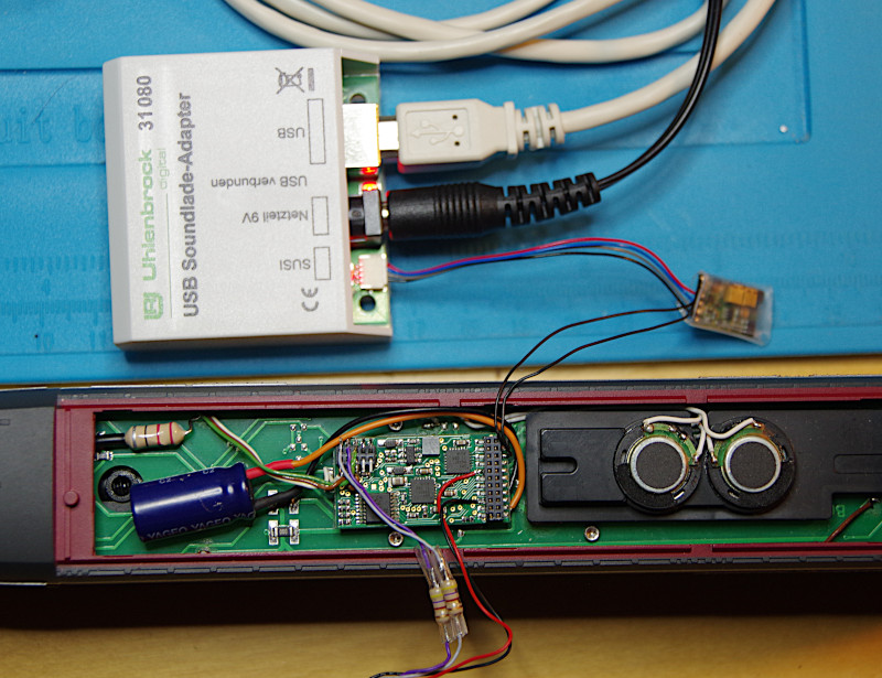
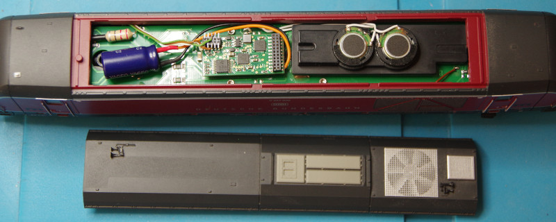
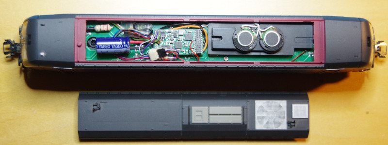
The following image shows the locomotive upgraded with SUSI3 sound. An Uhlenbrock IntelliSound 6 (32600) sound module was used. The sound module was wrapped in heat-shrink tubing and placed in the top left next to the CTC-Lokmodul-21mtc. The factory-installed speaker could still be used:
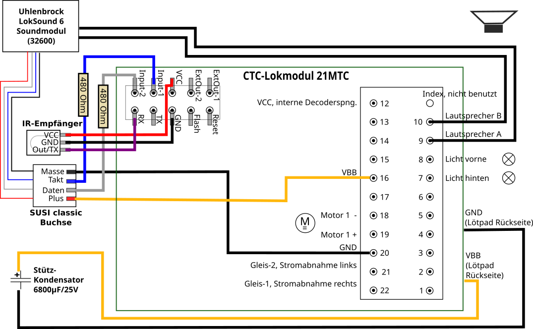
The corresponding wiring diagram is shown below; for details, see the user manual Chapter 9.1 – “Sound with SUSI Interface”:
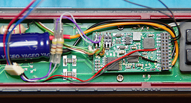
The following image provides a closer look at the wiring:
- The two black cables on the right side of the 21MTC connector are connected to the speaker output of the SUSI3 sound module.
- The two cables on the left side of the 21MTC connector provide power to the SUSI3 sound module (red = VBB = SUSI_Plus, black = GND = SUSI_Ground). VBB and GND are also available on the other side of the CTC-Lokmodul-21mtc as larger solder pads. However, since the buffer capacitor was already connected there, it seemed easier to use the contacts on the 21MTC connector.
- The 10-pin mini connector, previously only used for the IR receiver, is expanded with two additional connections:
- The purple (blue) cable connects “Input-1 (Pin 33)” on the CTC-Lokmodul-21mtc to the SUSI “Clock” (Takt) pin.
- The gray cable connects “Input-2 (Pin 32)” on the CTC-Lokmodul-21mtc to the SUSI “Data” (Daten) pin.
- The white socket in the bottom left is the SMD socket specified for SUSI3-Classic, where the cables could also be soldered directly.
In addition to the new firmware, an updated “ioCfg.xml” file is required, which must include the SUSI port configuration. With CTC-App 4.19, there is a new button in the configuration called “Replace IO-Config”, which can be used to apply this change (see Chapter 4 – “Configuring Modules”).
To reprogram the sound module, the SUSI connector is removed from the SUSI3-Classic socket connected to the CTC-Lokmodul-21mtc and plugged into the Uhlenbrock IntelliSound Charging Adapter: